
Raspberry Pi & Flying Toasters
Posted: August 11, 2022 Filed under: Uncategorized | Tags: afterdark, Macintosh, rpi, screensaver Leave a commentOver the weekend I was sitting in front of the ApplePi doing a little writing and surfing. I walked away for a while and when I came back the screen had blanked out. This is what Raspbian has done since it was installed and up until then I’d not really thought about it. However on this occasion it got me thinking back to the old days of elaborate screen savers, procedural graphics, matrix scrolling text and flying toasters. Anyone who ran AfterDark on their Mac back in the 90s, will vividly recall these flying chromium effigies and on the Amiga it was dancing lines. By 90s standards the black screen was duller than a rainy bank holiday, surely there was some way to spruce things up, that wouldn’t cripple the RPi3?
Consulting the Tinterweb
As what often happens in these situations, my train of thought led me down an internet rabbit hole, researching what screen savers were available for Linux, plus what would work on the limited resources of a RPi3. I do have a Pi4, but haven’t gotten around to installing it in the ApplePi, as with many things, it is on my “to do” list.
A cursory search online led me to xscreensaver, which offers a vast library of different screen savers, but most importantly one amongst them is titled “flying toaster”. This can’t be a coincidence surely, someone just happened to name one after an Afterdark screen saver?
When you initially install xscreensaver, it comes with a limited selection of built-in savers, if you’re betting Flying Toasters wasn’t amongst them, you’d be right. The interface itself doesn’t offer any advice regarding how or where to download the missing savers. So once more I turned to the internet and after a little searching, discovered this tutorial.
(https://pimylifeup.com/raspberry-pi-screensaver/) Most of it tread ground I’d already covered, however at the bottom the author was kind enough to include the commands for installing the additional screensaver data. In total the whole package and extras will occupy less than 100mb on your SD card, which isn’t bad when you consider how much it offers. Okay, by 90s standards 100mb for a screen saver is a little excessive, in fact it’s more than the average hard drive found in an Amiga back in the day. But that was then and this is now and as I write this, I’m already planning to upgrade the SD card in the ApplePi to a 128gb mSATA drive, once the RPi4 is installed.
Overall, xscreensaver takes up very little room on your SD card and in my opinion offers something a little more fun than a blank screen. While they once protected your CRT from screen burn, today’s modern flat panels have no such issues and the humble screen saver is more for decoration, than anything else.
Now you’ve read all that, let me walk you through the installation. First open a terminal window on your RPi and enter the following.
“sudo apt-get install xscreensaver”
Once your RPi has finished installing, you should find you now have a “Screensaver” option under your Prefs menu bar. If you like, load it up and take a look, you’ll notice a list of screen savers down the left panel, most of which will be greyed out. When you’re ready, enter the following command to finish installing the full package.
“sudo apt install xscreensaver-data-extra xscreensaver-gl xscreensaver-gl-extra”
And that’s all there is to it, you can load up the Screensavers window and select from a vast list of options, customising to your heart’s content. If you’re like me, you’ll get a buzz glancing across the room and catching glimpses of those silly toasters flying across the screen.
Until next time, keep on geeking!
ApplePi Update, now with ADB
Posted: September 26, 2019 Filed under: Apple, Macintosh, Raspberry Pi, Vintage Computers | Tags: adb, Macintosh, raspberry pi, rpi, teensy Leave a commentGreetings dear readers, today we are going to cover something I worked on at least two years ago but always felt there was room for improvement. I’m of course referring to my Apple Classic, super charged with a Raspberry Pi3b motherboard inside. Now before I continue, I want to make one thing clear, I only mod old computers that are beyond repair or have been gifted to me by friends in a state worse than death. So no working or repairable system is ever broken, we don’t rip SID chips off working C64’s around here you know! Anyone found doing so would be given a stern telling off and sent to bed without any beer!
So where was I? Ah thats right, the Apple Classic! So last time we visiting this topic, I had been gifted a partially modded Classic and by partial, I mean it had everything floating loose inside the case and was in dire need of TLC. The amp cut out when you cranked it up or worse took the screen out and the RPI2B was awful slow, emulating an old mac on it was not a nice experience. It now sports a reasonably nippy Pi3B over clocked to 1.3Ghz, emulating an 020 mac the Pi doesn’t even break a sweat, idling at about 45 degrees for both the CPU and GPU. Seriously I’m sat here typing all this on AppleWorks, running Mac OS 7.5.3 and it’s pretty much like using a supercharged Classic on steroids.
I might have to cover compiling and using Basilisk II on a Raspberry Pi as there isn’t that much written online about getting a decent build. It took me a few false starts until I was able to get the emulator working without mouse stutter. This could just be down to the fact I was trying to use a RPi2, which should theoretically be powerful enough, but past experience with my AmigaPi has taught me things are never straight forward.
Ever since I finished or almost finished the ApplePi, I’ve wanted to do more. I wanted to fit an internal ADB socket so I could use a real Apple keyboard for a start. Luckily there is code available online and with a £7 Teensy 2.0 board, I was able to solder together a USB – ADB adapter. ADB is a funny socket, in that its the same pin out as S-video, which means picking up connectors isn’t that hard. Plenty of people have made these adapters but most the time they’re either inside the keyboard or inside a tiny external box. That’s all well and good, but firstly you’re modding the keyboard so that it’s no longer ADB and secondly, I lose USB pens to my sofa on a monthly basis. I’d lose my keyboard adapter and not be able to type on my ApplePi! For me there was no question how I wanted it, the ADB port would go on the back of the computer, as part of the custom laser cut rear I/O shield. It wouldn’t be a true Apple + Raspberry Pi hybrid without ADB nestled along side the USB ports.

My Keyboard of choice Apple Keyboard II
For this mod I opted to use the source code by Shay Green (https://github.com/gblargg/adb-usb), while his code doesn’t include mouse support like some others did. I had think whether using a single button mouse was really all that practical in a modern Linux environment. I think I’d eventually tear my hair out with it’s limitations.
All in the Code
Programming the Teensy board isn’t that hard, you can do it on a Mac, Windows, Linux and the Raspberry Pi. To program a Teensy on a Pi you’ll need something called “Teensy Loader” (https://www.pjrc.com/teensy/loader.html). This software makes programming the tiny boards a breeze. On their website it says to run the program from the linux terminal, however I found this to be a fiddly method, constantly typing the same command in each time. Instead I made a script that allowed me to click an icon to load it up right away. Using a text editor of your choice, Nano (from within the terminal) or Text Editor from

Teensy 2.0
the desktop. Create a text file in the same directory as teensy loader, call it something like “Teensyflash.sh”. Inside the text file paste the following, leaving out the speech marks.
“./teensy &”
Save the file off and close the editor. Now assuming you still have the window open, you should see a new file called “Teensyflash.sh”. Right click on the file and select Properties and then select the Permissions tab. Next to the “Execute:” field, click the drag down menu and select “Anyone”. Click the “ok” button to close the window and save your changes. You’ve now told Linux this file is an executable, so next time you double click on it, Linux will ask if you wish to run it. Tell it yes and the loader should pop up, voila no terminal commands involved.
Using a Teens 2.0 not 2.0++
Unpacked, Shays program is designed to run on a Teensy 2.0++, if you have one of those fine skip this part. However I had a Teensy 2.0, the same board I used to make my custom USB Amiga Joystick last year. The two boards use different chipsets and as such will not run the same programs, you have to compile a HEX specific to 2.0 and 2.0++. If you wish to use a Teensy 2.0 board, you will need to edit a file before you can compile your HEX. Inside the “adb-usb-master” folder, you should find a file called “Makefile”, open it with a text editor and edit it to look like this.
#MCU = at90usb1286 # Teensy++ 2.0
MCU = atmega32u4 # Teensy 2.0/Pro Micro
#FLASH = teensy_loader_cli -mmcu=$(MCU) -w main.hex # Teensy
FLASH = avrdude -p atmega32u4 -c avr109 -P /dev/ttyACM0 -D -U main.hex # Pro Micro
Save the file off and close it, the program is now ready to compile for the Teensy 2.0.
I’m not going to bother covering using Teensyflash, as there is plenty of information online covering the subject, however I do wish to briefly go over building the hex file. This is essentially the program you are going to load in the memory of the Teensy, without it your dead in the water. When I first tried to compile Shay’s ADB software, my Raspberry Pi threw a fit, telling me I was missing files. It took me a while to nail down what I was missing, running the following command in the Linux terminal did clear up my problems.
“sudo apt-get install libusb-dev gcc-avr binutils-avr avr-libcapt-get install libusb-dev gcc-avr binutils-avr avr-libc”

heat shrink, prevents shorts
I think Shay’s code might expect the command line version of Teensy loader to be present in the same folder as his code, because after my Pi successfully compiled the hex, it threw up an error about not finding Flash. Don’t be too concerned about this as the HEX has still been created and is ready to load in the GUI loader.
Once you have Teensy Loader up and running, it’s just a case of loading in your HEX file, pressing a button and a mouse click later the program is stored on the tiny board. With the code loaded in the memory of the Teensy, it’s just a matter of wiring the correct pins together between the board and the four pin s-video connector. Given the size of the connector, I highly recommend using some heat shrink around your solder joints. This will prevent any of your wires shorting and frying your Teensy or Keyboard. A Data line is no place to stick your 5 volt input and certain components might take offense and die as a sign of protest. Then my friend you be wading in the brown smelly stuff without any wellies on! Don’t forget to solder a 1k resister between the data line and your 5v. Apparently some ADB cables suffer with signal drop and the 1k resister helps, if a jobs worth doing, do it right and fit a resistor!
After it was all wired up, I had to modify my rear panel as there was no  hole for the ADB port. With a lot of cursing and armed with a dremmel, I was able to make a half decent circular hole, just wide enough to accept the end of the ADB cable. Oh a word on plugging your Teensy to your computer, make sure you use the cable that came with it. I made the foolish mistake of using a spare mini USB cable I had laying around, the darn thing wouldn’t load up properly. Twenty minutes spent testing for breaks in my wiring and it all came down to a tiny USB lead.
Conclusion
When it works, the ADB-USB adapter is amazing, switching from a Bluetooth Apple Keyboard to an original Apple Keyboard II is a massive difference. It feels better, keys are spread out and in general I’m not finger typing any more. It also looks a million times better in front of the ApplePi, seriously you would be forgiven for thinking it was a real Apple computer when Basilisk II is running. Shay Green has my thanks for posting the code

A new panel to cover those holes.
up that made this hack possible. Were it not for him, I wouldn’t be sitting here typing to the sound of klacky keys! Thanks dude!
Next up I shall be designing a rear panel to cover the holes left behind by the old power switch and power socket. In their place, I plan of installing a control panel for the IPS screen, allowing me to change the brightness, contrast etc.
MegaPi Zero
Posted: May 24, 2018 Filed under: Linux, Raspberry Pi, Retro gaming | Tags: emulationstation, megadrive, pi zero, raspberry pi, raspbian, rpi, Sega Leave a comment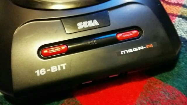
The MegaPi
Not long ago I bought myself a NESpi and was telling a friend about it. She went on to ask me if there was a Sega equivalent, as her brother was an avid Sega fan growing up. Sadly I had to tell her there wasn’t but that added, that building such a console wouldn’t be that difficult, me and my big mouth. Thus I found myself with a new project on the drawing board, added to all the other projects I was tinkering with. When will I learn?
Having built the NESpi and my Picade, I knew EmulationStation could easily accommodate my needs. Not only can it emulate the MegaDrive, but the Master System, GameGear and SegaCD as well. The only real question was what platform I would use for all the grunt work. A Pi3 seemed a little overkill, true it would handle anything thrown at it, but it also hiked up the cost of the build and I was trying to keep to a budget. I might have been able to pick up a second hand Pi2b, however they seem to sell close the what they cost new. I didn’t want to go down the clone route as support isn’t as good, so that left me with one option, the Pi Zero. I’d never tried using a Zero for playing games, messing about with electronics yes, but gaming just seemed a little to demanding for BCM2835 processor. However if you read up on the Zero, for such a tiny board, you realize its actually quite powerful. Clock at 1Ghz, the CPU is approximately 40 percent faster than the same chip inside the original RaspberryPi. Tests have shown the Zero operates roughly four times faster then the original Pi. While I was never going to see Pi2 performance, it would hopefully be enough to emulate the MegaDrive. It seems a little crazy that a 1ghz 32bit processor shouldn’t be capable pf running 30 year old software, but we have to keep in mind, that the Zero is being call upon to accurately emulate a whole console. Translating sound, display, input on the fly, into something close to the real thing.
Building
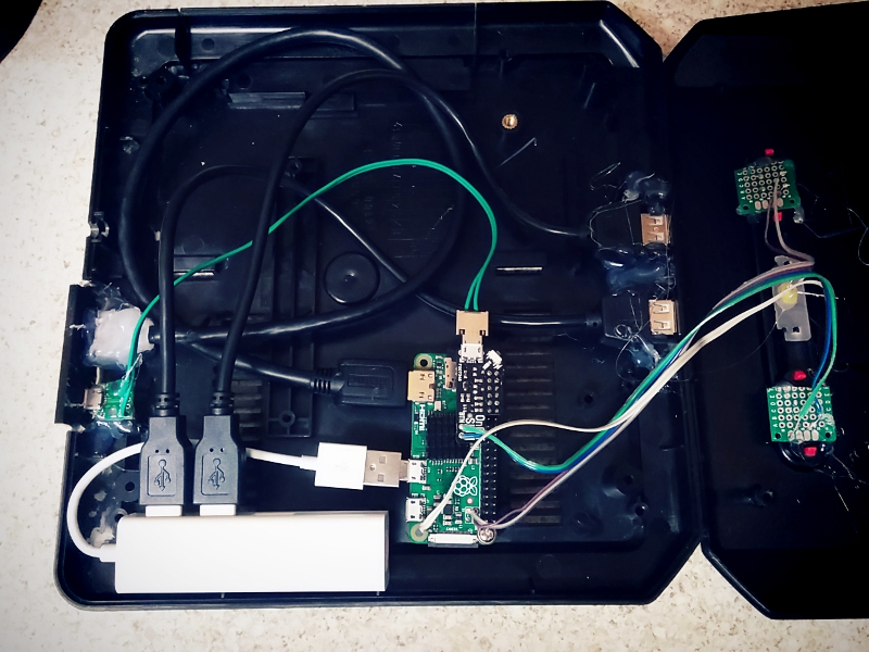
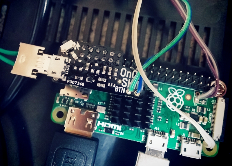
From the beginning my intention was to alter the MegaDrive very little, in fact I wanted to replicate the consoles original functions. Allowing the Power and Reset buttons to work pretty much in the same way they had before. I was able to make this possible using Pimoroni’s on/off shim, this tiny board sits atop the Pi’s GPIO header and allows you to safely shutdown the computer with the touch of a button. It also comes with through holes, allowing you to solder your own button to the board. The shim is pretty versatile, you can either use the included header block or solder the shim directly to the GPIO header, thus freeing up the GPIO pins if say you wanted to use another HAT, like a PHAT DAC. Once installed, for the shim to function you must plug power in to it directly and not in to Raspberry Pi. That way power is being fed through the shim in to the Pi via the GPIO header, putting the shim in control of feeding power to the Pi. The added bonus to all of this, is that your bypassing the Pi’s annoying poly fuses.
With the power sorted out, the next step was the Reset button. The Zero, like other Pi’s comes with a pair of through holes labeled ‘RUN’. If you short them, the Pi’s CPU will halt what it’s doing and reset the system. Ordinarily this isn’t something I would recommend doing regularly, as you run the risk of corrupting your SD card. However, if your running a Pi and for what ever reason it locks up. If your only input devices are two joypads, a reset button might just be what you need to get back on track. This was first time I’d ever wired up a reset button on the Pi and later was thankful I had, as on one or two occasions EmulationStation locked up because I’d done something stupid.
Out of the box, the Zero comes with only a single micro USB port, which isn’t much good if you want a two player game of GoldenAxe. To work around this problem, I used a compact USB hub, specifically suited for the Zero as it came with molded micro USB connector and not a full size USB plug. I then used a set of cables to extend two USB ports to the front of the console, where the joystick ports had once been. I also made a custom power lead, one end going to the rear of the console as a dedicated power socket and the other going in to the on/off shim. Always use thick gauge wire when extending the Pi’s power socket as it only take a little voltage drop for the dreaded ‘undervolts’ icon to appear in the top right hand corner of your screen.
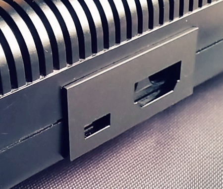
For the rear panel of the MegaPi, I designed a custom I/O panel to replace the Megadrives existing RF and Power Jack with micro USB and HDMI. After cutting out the existing panel, I hot glued the laser cut acrylic panel in place, along with the cables coming from the Zero. I applied a copious amount of glue to both sockets, especially the HDMI port as I found it a little tight when I was hooking up my TV.
Press My Buttons
I’ve already mentioned how I was able to get functional Power and Reset, but getting both to work with the cases existing buttons was a challenge unto itself. First I began with two tall 6mm tall micro switches, which I soldered to strip board and later trimmed to fit the area under both red buttons on the case. It took a little trial and error, trimming the height of both micro switched until they worked properly with the buttons. When I had both working to my satisfaction, I used my trusty glue gun to affix them to the underside of the top lid. Glue guns are by far, the makers best friend!
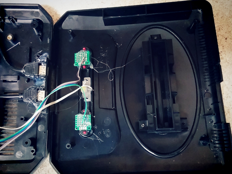
With the both switches in situ, all that was left to do was connect them up to the pi itself. A quick test, proved both worked as desired and so the next task was setting up the software.
EmulationStation
Without a doubt, building the Megapi would have been a very different story if it were not for EmulationStation. Setup and configuration of this software has been made very simple, allowing even the most inexperienced to follow it. Configuring the Sega style USB controllers I’d bought was a little fiddly but trial and error eventually prevailed and I had both working as desired. I was even able to setup a custom loading screen and Sega themed booting screen. The first time I came to try out a game, I was really surprised by the performance. The Zero handled most games I threw at it, struggling only once or twice, I doubt very much it could handle any of the 32x or SegaCD titles. But as a bog standard Megadrive it copes pretty well, better then a £5 computer really ought to. But it just goes to show what good value the Zero is and what it possible with such a cheap, tiny computer. I’m really glad the foundation developed the Zero, with the increasing speed of the larger Pi3b and now 3b+, it stands as an affordable foot in the door. Had the Zero not be around, I probably would have tried to buy a cheap second hand Pi2. For the simple fact that the Pi3 was too expensive and powerful for my needs. That being said, I’m not even certain the larger Pi form factor would fit inside the MegaDrive II case.
Conclusion
This was a fun project and not one I would have made had it not been for my friend asking. Truth be told, once built, I grew really attached to it and was sad when it came time to hand it over for my friend to give her brother. From what I gather though, he really loved his birthday present. Hopefully he’s reliving his childhood, maybe even having a mate over for a few beers a game of sensible soccer or Sonic and Tails.
The on/off shim is available via the Pimoroni website at
RPi SD Card Failure & Booting from USB
Posted: February 8, 2018 Filed under: Linux, Raspberry Pi | Tags: boot raspberry pi from usb, linux, pidp8i, raspberry pi, rpi Leave a comment
Card corruption isn’t anything new on the RPi, if your a Raspberry Pi owner it is a fair bet that you shall encounter it eventually.
Over the years ever since owning my first Pi, I had to deal with the occasional segmentation fault. But I’d never encounter a full blown SD card failure until the other day, when quite unexpectedly the PiDP8/i decided to have a system melt down. The first signs indicating something wasn’t quite right, was when I discovered my fail2ban jail log was corrupt, full of complete gobbledygook. After a reboot of the server, I discovered everything was back to normal or so it had seemed. The next indication problems lay ahead was when I noticed files I’d previously deleted had reappeared on the SD card. Now if there’s one thing Linux is good at letting the user do, it’s delete precious files without much chance of recovery. I once deleted an entire partition of my hard drive by mistake and yes, spent what was left of the night reinstalling Xebuntu. Linux is a powerful OS in the right hands but for the experienced it can be a steep learning curve of mistakes and mishaps.
After spending a full day working on my SD card, I discovered sure enough that the internal 8GB card had died a death. I read from the drive, but could neither format or re-partition it.
So what now? Well my next step is going to be getting my hands on a new SD Card, but I’m not so certain I feel comfortable using it as the primary storage on my PiDP8/i server. Everything I’ve read online indicates using SD cards for prolonged periods is not a great idea, mainly due to the limitations of the technology which doesn’t lend it self to constant read / writes. It’s worth remembering that ever since the first compact flash drive, memory cards were originally intended for cameras and PDA devices, neither of which really hammer the SD card unlike Linux. SD cards have a finite number of read / writes, from the time you plug it in, your memory card is degrading. On a short time project this isn’t a problem and there is evidence to suggest capacity does play a part, with larger cards such as 32, 64 and 128gb lasting longer then 8gb ones. Still if I want my server to be online 24/7, I’m better off finding a more reliable and permanent solution.
A hard drive is one I guess, but a little bit overkill for the tiny PiDP8/i. Which is why I’ve spent the past few days looking up ways to boot the Pi2 model b motherboard from a USB flash drive. Research suggests boot time will be faster and reliability significantly better then using SD. So in my next article I’m going to cover the process of setting up a RPi2 model B with the OS installed on USB pen. If your a Pi3 owner you have two choices, you can follow what I’m doing and it should work just fine. But unlike earlier models, the Pi3 can boot directly from USB by altering the OPT within firmware. Once enabled the Pi will search SD and USB until it finds a bootable partition.
Building A Portable Pi
Posted: April 11, 2017 Filed under: Linux, Raspberry Pi, Vintage Computers | Tags: adafruit, portable pi, powerboost 1000c, raspbian, rpi Leave a comment
For a long time I’d thought about creating a portable Pi but wasn’t really certain where to begin, so for a long time it remained just an idea rolling around in my head. After building the 600Pi I developed a greater understanding of what was involved fitting a Raspberry Pi inside a custom enclosure, such as extending the USB, HDMI and Ethernet from the tiny Pi and how to power the motherboard directly, bypassing the traditional on board USB port. The 600Pi really opened my eyes and taught me a great deal, not just about wiring, but also about hacking the Pi’s various features. A month or so after finishing that project a friend gifted me a box full of random bits, because if there’s one thing friends know about me, it’s that I love boxes filled with parts. Inside was an assortment of USB cables, fans and a RPI2 B fitted in a custom acrylic case. What caught my attention about the Pi specifically was the 3.5″ LCD panel that was attached to it, as soon I saw the screen the cogs in my head begun to whirr. Well suited for a portable pi project, it was just a matter of me drafting up a design.
A few weeks after receiving my box of goodies I was clearing out a bunch of old stuff from under the bed when I found an old project box lurking under the mattress. A left over from when I was designing my Nomad desktop system, it was just the right size for a portable retro computer, not to mention it already looked kind of old. Originally there had been two but I’d hacked one up for the Nomad, only to find it had very little air flow and caused the mini ITX board to overheat. However, unlike the larger mini ITX board, the Pi not only had a smaller foot print but would never reach the operating temperatures of an Intel Duo processor.  At first I wasn’t certain the LCD panel would fit in the front of the case, but pairing the two together proved it would be a snug fit.
Admittedly, building a portable Pi isn’t anything new, people have been putting them inside all manner of things ranging from teddy bears, tea pots, remote control drones and even coat pockets! You can find Pi powered laptops, C64s, Spectrums and even 3D printed Gameboys like the Pi-GIRRL, however my goal was to build a portable computer with a distinctive 80s retro feel, bet you didn’t see that coming did ya! Using a case originally intended for my Nomad desktop, I decided to call my new portable the ‘Nomad SX/Pi’ in homage to my earlier project and also the Commodore 64SX portable computer, a machine I was drawing much inspiration from.
Design
 It’s probably no surprise the SX64, Keypro, Osborne and even the TRS80 M100 inspired the design of my project. All are note worthy machines, successful back in their day with a dedicated group of followers even now. Their appearance resonates a specific time in computer history and it was this aesthetic styling that I wanted the Nomad SX to imitate. Measuring 257 x 190 x 85mm the case had ample space for the Raspberry Pi, however the 3.5″ LCD was another matter. It was almost as tall as the case with only 10mm clearance between the top and bottom lid. As I had done with the 600Pi before, I extended the Pi’s ports to the front and rear panels of the case. Included in the rear panel was:
- 1 x USB
- 1 x RS232
- 1 x Ethernet Port (Rj45)

Front panel with USB and audio
- 1 x MiniUSB (Power Input)
For the front I extended the Pi’s audio jack and another of the USB ports along with the Pi’s power and activity lights. Having only recently upgraded the 600Pi with a new Pi3, it meant I had spare Pi2 board with the on board LEDs already modded for extending to the front panel. The reason I didn’t extend all the USB ports was because I needed two of them for Bluetooth and Wifi.
After making a couple of rough sketches I sat down, using Inkscape to draw up the vectors I would need to cut the front and rear panels out of acrylic. Previously I’d used an old version of Adobe illustrator, but a couple of my friends kept insisting I gave Inkscape another shot, even though I’d struggled with it the first time round. My initial impression of Inkscape was that it was powerful but far less intuitive then Illustrator,, but it does have one thing working in its favour. Unlike Illustrator its an open source freeware application, meaning it doesn’t cost you a penny to use.

Better view of the rear panel
Installing it on the Nomad, I spent the evening drawing the panels using the sketches I’d made earlier. After a some what slow start, I actually found Inkscape to be pretty straight forward and not as complicated as first thought. In fact once your in the Inkscape zone it’s actually a pretty powerful application. Available for Linux, Mac OS and Windows, I highly recommend checking it out and did I mention its available for the Raspberry Pi?
Input / Output
One part of the case that was causing me a headache was the keyboard, originally I’d wondered if I couldn’t buy a small keyboard and hinge it to the front of the case similar to the Keypro or attach it with Velcro. However that meant finding a keyboard with the exact same dimensions as the front panel which was highly unlikely. Unlike large manufacturers that can fabricate custom parts, I was limited to finding off the shelf parts to get the job done. After a lot of searching on eBay, I found a wireless keyboard and waited patiently for it to arrive from China. Almost as soon as I unboxed, I realised it was rubbish,

3.5″ of retro goodness
surprise, surprise. The touch sensitive panel was smaller then I’d expected and pretty useless for typing anything. That is unless you wanted to finger type everything, which as I found resulted in almost inebriated sentences of typo ridden nonsense. So it was back to the drawing board and searching once more online for a suitable keyboard, a search that had thus far been less than successful. It turned out I hadn’t needed to worry as only a couple of days after my disappointing eBay purchase, my prayers were answered. While picking the other half up from work, I was telling her about the problems I’d been having when suddenly she revealed her work stocked several bluetooth keyboards on their online shop. A quick trip across

2.4Ghz wireless and sadly disappointing
the warehouse floor and I was staring face to face with an ultra slim bluetooth keyboard and not just that, it was narrow! Talk about irony, I’d spent the best part of a month looking for one under 250mm wide and all the while Pimoroni had exactly what I’d wanted on their website and it was 240mm wide, 10mm shorter then the case I was using.
With the issue of the keyboard finally behind me I was able to redesign the front and rear panels to accommodate the new BT keyboard. Originally I’d planned for the little touch panel keyboard to slide inside a slot in the front, but as that wasn’t happening now, I had to find room to accommodate the larger 240mm x 90x 14.5mm keyboard. Barely 10mm narrower then the case, I had to come up with a smart way of stowing it away. Strapping it to the outside would undoubtedly expose it to unwanted knocks which would likely wear it out in no time at all. Don’t ask where the idea came from but scribbling on a piece of paper I found myself staring at a sketch of the rear panel with a narrow slot for inserting the keyboard inside. Refining the design further resulted with a shelf inside the portable for the keyboard to rest on when it wasn’t in use, I also designed a blanking plate to screwed in place over the slot to keep the keyboard from sliding out while the computer was being transported. While it wasn’t like anything I’d seen on the Z80 portables I’d been using for reference, it certainly worked and solved the problem of where to put the keyboard.

Rear panel went through several revisions before it was right
As there was no need for a slot in the front panel I redesigned it, turning it in to a sliding door and IO plate for the audio jack and USB port. Taking advantage of the reclaimed space I also included a badge to sit above the IO panel which read “Nomad Pi/SX – Portable Micro Computer”. It seemed fitting given the size of the Raspberry Pi computer hiding inside the case.
Bluetooth Woes
Setting up an Ultra Slim keyboard on the RPi wasn’t as smooth sailing as I’d been expecting and required some work before it was up and running properly. I also encountered an annoying problem where the top row of F keys weren’t recognised by Linux, even asking the guys at Pimoroni and on the RPi forum yielded no solution. Two months after finishing the portable Pi I was at a friends sampling a pint of homebrew beer when the answer came to me. I don’t completely recall what led to the discovery (how strong was that beer?), but long story short Linux was mistaking the ultra slim keyboard for a BT Apple keyboard. It turns out these are known for having issues with Linux and there’s even a wiki page covering it, see this link for details.
LCD Screen

Adafruit Powerboost 1000C, a fantastic little PCB
For the Pi’s composite video jack I used a 3.5mm jack cable, splitting the left, right and video lines. I hooked the video feed up to the LCD panel and the audio channels to the audio socket attached to the front panel. At some point I plan on installing internal sound but that will be a work in progress. When I discovered the PI / LCD combo, I originally wrote down the wiring so that I’d know how to connect it back up. Like any scrap of paper it inevitably went missing and not knowing the model of the screen or where my friend had bought it, I was left in a bit of a pickle. How was I ever going to figure out the wiring? Luckily for me I’m on the Sheffield Hackerspace mailing list and after posting up a request for help, I soon had a link providing me with all the info I needed to connect up my tiny screen. Words honestly can’t do justice for how grateful I was when the tiny LCD lit up for the first time, so a big thank you to the guys at the Sheffield Hackerspace.
Because I was planning primarily to use the terminal and not x.org to operate the Pi, I found the text on a 3.5″ screen a little difficult to read. Online I found several guides showing ways to increase the text size within the Linux console, and I also read up on altering the screen resolution which was running in its default res of 1080p (I guess). Either way it was causing the 3.5″ screen to flicker at a headache inducing rate. Fortunately the config.txt is pretty flexible and allows you to tailor a lot of the Pi’s settings to suit your needs, which is great for anyone trying to use a 3.5″ screen with their Pi via composite out.
Tackling Small Screens
Having only ever hooked a Raspberry Pi up to a VGA monitor, I’d little experience configuring the config.txt file to display on a small screen. Especially one using composite output instead of HDMI. Fortunately there’s plenty of information available online to walk you through setting up the config file and a bit of trial and error I was able to get it working. By setting the screen to 480×320, I was able to eliminate almost all of the screen flicker present while the screen was running in high resolution. Additonally making it much easier to read text, as even in 800×600 it was incredibly small. Though lowering the resolution made the text more legible it still  wasn’t suitable for using over an extended period. This led me to looking at changing the Terminal itself and how I could configure it to display differently on the Pi Portable. Fortunately you can alter the Terminal using the following command
"sudo dpkg-recofigure console-setup"
Going through the prompts I set the terminal to use the ‘TerminusBold’ font at a size of 11×22 as this was easy to read and didn’t take up to much room on the screen. It took me a while to figure all this out and I went through several computations of the various fonts and sizes before I found the right one. While doing a little research for this article I discovered one of the machines I’d used for inspiration has a larger screen than I’d first assumed. The Osborne-1 is often cited as the first portable personal computer and it along with the SX64 were machines I used as examples while designing the Nomad SX. As it turns out the 1981 Osborne-1 came with a 5″ screen capable of a mind blowing 128×32 character display. Which is impressive compared to the 11×22 display on the Nomad, if I ever make another portable I’ll be sure to make the screen bigger!
Not A Leg To Stand On
After getting the machine together I realised the viewing angle wasn’t exactly ideal. In fact to read the screen I had to prop a book under the case. I’d not really envisioned using a stand like the SX64,  but as it transpired I actually really needed one. If I’d stopped to think back about all those old Z80 machines, a large number of them did come with a kickstand of some sort. Designing a set of legs I got them laser cut from acrylic and fitted to the sides of the case. I used nylon lock nuts so that I could tighten the screw enough so the legs were stiff to move, but with the advantage that lock nuts wouldn’t work themselves loose. The downside to using acrylic is that under certain circumstances it can be a fragile material and exposed to stress will sometimes shatter or crack. As the legs would be in regular use, I wasn’t certain how long the acrylic would last. With that knowledge ever present in my mind, I spent a lot of time trying to think of an alternate solution. Eventually I settled upon 3D printing and fabricating a single piece carry handle, as you can see in the picture the prototype came out pretty good.
Being Portable Means Being Portable

Part of this project was to make a portable micro computer that I could take with me wherever I liked. This ultimately meant using a battery, something I’d never done with a Pi before. So once I had the system working and all of the internal wiring finished, I began looking at batteries and also charging circuits. Obviously because of the screen, bluetooth & wifi dongles, I would need a pretty substantial battery to power everything. It was around this time that Pimoroni began stocking batteries via their online store. I also noticed they stocked the Adafruit Powerboost 1000C, a small 5v 1Amp board that doubled as a battery charger. Choosing one of their 4400mAh batteries and the power boost, I set about modifying the internal wiring of the Pi Portable. Instead of the power going directly to the Pi it would have to go via the Powerboost first, so that the internal battery could be charged.
I’ve seldom bought anything from Adafruit aside from perhaps a micro usb socket but I have to say the Powerboost is a fantastic bit of kit and really does credit to Adafruit. Not only was it straight forward and simple to wire up but I found the additional

A sneak peak inside, yes its crammed.
power switch an especially nice feature, one that I hadn’t been aware of at the time of purchasing. It was certainly a lot better than pulling the plug, as is the normal way to turn off your Pi after shutting it down. As the back panel was in need of revision due to some stress cracks showing, I added an additional hole for a switch, which complimented the rear panel really well, giving it a very professional look. Combined with all the accessories, the Pi portable draws approximately 740Mah, which means I should get nearly 5 hours out of the 4400 battery. I’ve yet to actually bench test the Pi portable to find out if those figures are anywhere near accurate, but even if the system can manage 2 hours, I will be happy and consider the upgrade a success.
Closing Thoughts
While it might not be as sleek or as compact as many other portable Raspberry Pi builds. I’ve taken the Nomad Pi/sx to several retro events and had nothing but positive feedback. Many remember using machines like the SX64 and Osborne back in the day and instantly latch on to the similarities. Loading up Dizzy via the C64 emulator never fails to generate a smile. But if I’m honest, I always end up playing Outrun or Stuntcar racer!
This has been a funny old build but one I’ll definitely remember if not for the fact that I do use the computer on and off when I need a distraction free typing environment.

Raspberry Pi Winamp
Posted: November 19, 2015 Filed under: Linux, Raspberry Pi | Tags: linux, promoe, raspberry pi, rpi, winamp, xmms2 5 Comments
Ah Linux, how we do love you, but why oh why are we forsaken to never enjoy a media player such as Winamp! I mean Parole is good, VLC isn’t bad either..But still, it isn’t Winamp is it? If your like me, then the Llama kicking audio player will be one of your staple apps. Its been on every one of my Windows machines for the past 12-13 years. So imagine my disappointment when I started using Linux 4 years ago and didn’t really find anything remotely like it. Fast forward to present day, last Monday to be precise and I’d got my newly built Amiga 600PI running pretty well, the only thing missing was a kickass mp3 player. After doing a search online, I found plenty of people in the same boat, they liked Linux, but they missed Winamp. After doing a little more digging I learned about XMMS2 and the interesting things people had been doing to make it look like Winamp. Rolling up my sleeves, I gave it a go and while it wasn’t totally straight forward on the Raspberry PI, the results were still pretty successful, so read on.
The first thing you need to do, is install XMMS2 and Promoe client. I did this via the synaptic package manager. Which you can download via this terminal command.
Sudo apt-get install synaptic

When you have it installed, open it up and find these files. XMMS2 Promoe Once you have those two files installed, you will find Promoe is now listed in the Sound & Video section of your start menu. Run Promoe at least once, simply to test it works and also to allow XMMS2 to initialize itself. When your done, close the program and we’ll move on to the next step.
Audacious Classic Winamp skin, kicks the Llama’s ass!
Luckily the skins for Audacious seem to work on XMMS2 or perhaps thats the other way around, XMMS skins work with Audacious. Eitherway we need a classic Winamp skin to proceed, so go online and download the classic skin here.
Winamp+Classic+skin+for+Audacious
You should now have a file called “135799-winamp_classic.wsz“, make a new folder and call it ‘Winamp’, extract the archive inside it. See pic Right now here is the part where I hit trouble. According to everything I read online, Promoe stores its skins in the following location.
“/home/pi/.config/xmms2/clients/promoe/skins”
At least it would, if the location existed, which is didn’t on my system. When I navigated to the xmms2 folder, I discovered the ‘clients’ folder wasn’t there.
Here’s a handy tip if your trying to find a file or folder in on your Raspberry PI
find / -name filename 2>/dev/null
Swap out ‘filename’ for the name of what your looking for, press enter and wait. Your PI will now go off searching the entire SD card in search of your file. I used this to search for the missing ‘clients’ folder.
Even if the folder structure doesn’t exist, Promoe was still instructed to look in that location. So the best thing to do is make the directories ourselves, as Promoe will then find any skins we want to install. Because the xmms2 folder is a root folder, we’ll need root access to make alterations. Open the terminal and type
sudo nautilus
A new window will open up. You’re now navigating the file system with super user access, so be mindful young padwan. As one wrong keystroke or click here and you could break the entire operating system. And trust me, you really don’t want that! From the top menu, click ‘View’ and make sure “Show hidden files” is enabled. Now on the left panel, click on “File system”. Find the icon named ‘Home’, open it and then open the folder called ‘pi’. Next find a folder named ‘.config’, it will only be visible if you have ‘Show hidden files’ selected. Open the folder and scroll down until you find ‘xmms2’. Open the folder and from the top menu, click ‘File/Create New Folder’, name the folder ‘client’, making sure to keep it lowercase.
Open the ‘client’ folder and create another folder, this time name it ‘promoe’,

Should look like this
again all lowercase. Still following me? good, because we are almost done. Finally within ‘promoe’, make one last directory and name is ‘skins’. All going to plan, you will now have the follow directory structure;
“/home/pi/.config/xmms2/clients/promoe/skins”
But wait, we aren’t finished yet, we still need a skin to put inside the skins folder. If you downloaded the one I mentioned earlier, you need to copy the ‘Winamp’ folder in to the skins directory. The simplest way to do this is a drag and drop. First open the ‘skins’ folder you created, then from the start bar, open a new file manager window. Locate your ‘Winamp’ folder and drag it over to the open ‘skins’ folder. Now let us see if it all worked, fire up Promoe, by default it uses the Almond-blue theme. Click on the little blue box in the top left of the interface, from the drop down menu, select ‘Theme settings’. You should now see the Winamp skin listed, click it and voila! Winamp Classic on your Raspberry PI!

You can now close all the other windows, especially the one displaying the ‘skins’ folder. Once closed, it will terminate your root access and once more protect your system from any accidental clicks. Until next time, keep on geeking!
Pimoroni Pihub Review
Posted: January 31, 2014 Filed under: Linux, Raspberry Pi, Windows | Tags: hub, pihub, pimoroni, raspberry pi, review, rpi Leave a comment
PiHub By Pimoroni
As some of you know, I dabble on an off with the Raspberry Pi. As a casual user, I use my pi mostly for playing with linux and the odd gaming session. The Pi is a fun little computer, so long as you don’t expect to much from
it. As an indie games platform it offers a lot of fun, so much that I have even felt myself being drawn to writing a program on the tiny computer.
Anyone who has used a raspberry pi for any length of time, will know that cables can soon start to mount up. It’s amazing that such a tiny computer can take up so much room. The RPi can work fine as a stand alone computer, but start adding a wifi dongle, keyboard, mouse, USB memory stick, card reader and suddenly you’ve run out of USB ports. There are solutions to get around the RPi’s two usb ports, but none of them are simple or straight forward as buying a powered USB hub. First and foremost if you buy a hub for your RPI, you have to get one that comes with its own power supply.
On early models of the RPi, the USB ports were fitted with polyfuses designed to protect the tiny computer from devices that might try and draw too much power, such as external hard drives or web cams. Later models did away with the two fuses and now the RPi has just one fuse. While the latest design has improved matters, you are still stuck with just the two ports which is where a power hub like the Pihub comes in, alleviating your power woes and freeing you from two port hell. The Pihub is the creation of Pimoroni, the UK company that also brought us the Picade. Their website offers supplies to a wide audience of tinkerers, modders and electronic hobbyists. One of their recent offerings to the RPi community was the Pihub, aptly named as the housing of the Pihub is in the shape of the Raspberry Pi emblem. Adorned with green leaves and red berry colours, as hubs go it is by far the cutest I’ve seen. The case is but one cool feature of this little device, and the hardware inside is pretty impressive as well. When buying your Pihub, you have the option to opt-out of buying it with the accompanying power supply. While this might seem like a good way to save money, I would recommend spending the extra money for the PSU as it is well worth the money. Rated at 5.2 volts and 3mA/h, it is more than capable of powering the RPi along with anything else you might want to throw at it. Struggling with external CDROM drives and USB hard drive are a thing of the past. 
Unimpeded by polyfuses like the RPi, the Pihub offers the full USB 2.0 package, with a multi TT (transaction Translator) chip for bringing USB 1.1 devices in line with the high bus speeds of USB 2.0. Some devices use only
one TT chip, sharing a single 12mb/s data channel amongst several USB ports, which can significantly impede your performance and lead to a bottle neck effect, unlike the Pihub which has been designed to provide high performance. Designed with 4x USB ports, one of which is specifically engineered to power your Raspberry Pi
computer. Providing a dedicated 1.1 Amp supply, it means no longer needing two separate power supplies, you can run everything from just the one psu. For me this is a massive selling point because I found the increasing number of bits i needed for my Pi really annoying. My desk has been turned from crazy cable jungle to almost down right respectable. While yes, powering the RPi from the Pihub does mean your taking up one of the ports. You’re still left with three full USB 2.0 standard ports as well as the spare port on your RPi. Overall I think the trade-off it worth it.
Speaking with Paul Beech from Pimoroni, he informed me the Pihub had specifically been designed with high quality chips to guarantee 100% compatibility with the RPi. This is no doubt due to the number of cheap hubs on the market, that are less then RPi friendly.  In an odd turn of events, I actually observed how compatible the Pihub really was in general. After plugging my wifi dongle and mouse in to the Pihub, I connected it to a Windows XP machine. On booting, XP didn’t even ask for drivers, instead logged me straight on to the local area network through the wireless adaptor. I’ve seen few hubs work this seamlessly. High praise has to go to the chaps at Pimoroni. In conclusion, the Pihub is well worth the £20 if you’re on the market for a decent usb hub for your RPi or PC in general. 10% of profits are given back to the Raspberry Pi Foundation, who use the money to help educate future generations of geeks.
Till next time, keep on geeking!
The Pihub can be found via the Pimoroni store at
http://www.pimoroni.co.uk
