
Atari Lynx Screen Mod By McWill
Posted: April 21, 2017 Filed under: Atari, Classic, Handheld, Retro gaming | Tags: Atari, Lynx, mcwill, screen mod, screen replacement Leave a comment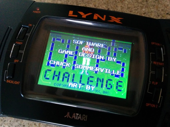
The Atari Lynx arrived on our shelves 27 years ago in the winter of 1989, only two months after Nintendo released the Gameboy and a year before the Sega’s colour handheld the GameGear saw light of day. Featuring the first backlit colour screen on any portable gaming device, the Lynx boasted accelerated 3D graphics.
Developed by former Amiga designers R, J Mical and Dave Needle, the ‘Handy Game’ came about after former Amiga manager David Morse approached them about designing a portable gaming system for Epyx. In 1989 faced with financial difficulties Epyx found itself partnered with Atari Inc, who agreed to handle production of the ‘Portable Colour Entertainment System” leaving Epyx to handle software development. Between 1989 and 1995 the Lynx was reported to have sold 3 million units world wide, but ultimately failed to beat the Gameboy even though technically superior in many ways. The Lynx is a fantastic system to add to any collection with 72 games released officially, varying from run of the mill to great titles like Chip’s Challange,

Lines the bane of any Lynx owner
Todds Adventures in SlimeWorld and California Games. However like most systems from this time its not without problems, the most predominant of which is screen failure. Usually this appears first as one or two lines running vertically or horizontally across the screen, more follow until the display is unusable. The root cause of this is the ageing ribbon cable that links the logic board to screen, over time becoming fragile and brittle. As it is an integrated part of the LCD display the only way in which you can cure the fault, is by swapping to screen for a new one. Which wasn’t a problem back when the Lynx was new, but in 2017 you might be faced with a problem, that is until now.
A Proper Solution

Stock screen looking less then great.
On AtariAge back in 2015 a user by the name of McWill came up with an interesting solution to solve the problem that had been plaguing so many Lynx owners. By developing his own custom display board he was able to replace the old failing screen with a modern LCD which not only offered superior picture quality but an optional VGA out. Unsurprisingly the board was an absolute success with Lynx owners far and wide, who finally had the means to repair their ailing consoles. Last year I was lucky enough to buy one of McWills kits, the board requires some self-assembly and a reasonable understanding of how to solder is needed. McWill does offer and installation service for those who don’t feel confident installing the kit by themselves. I was completely blown away with the image quality, which is ten times better then the original 90s LCD. The picture is sharp and the back light more linear, the full screen is now illuminated and gone is the incandescent tube glow of the original florescent light. The new screen uses modern EL technology which has come on leaps and bounds from when the Lynx was originally released. Ghosting and trailing has been significantly reduced, if not illuminated compared to the original 90s screen. If like me you’re accustomed to viewing your games on the old screen, seeing them for the first time on the new one can be a pleasant if not slightly shocking experience. I was honestly left wondering how the heck I’d managed for so many years without McWills screen mod.

McWills screen, there’s no denying the difference.
Priced at around 100 Euros the kit isn’t cheap however if you figure in the fact you’re getting a custom printed PCB and LCD its actually not bad value for money. The PCB is well made and laid out easy enough for even the budding amateur to follow. However the single sheet manual could have been written a little better as I stumbled to following it wiring to the TPR solder point. The wiring for this can depend on your model of console and what I didn’t know at the time was that I needed to close a jumper on the custom PCB. Labelled in small print as JMP1 in the printed manual its easy to miss and nowhere else is it referred to by this name. For instance here is an excerpt from the instructions.
‘For LYNX-II with chipset 1 (C104129-001) you have to use TPR (testpoint 27) only. For using TPR jumper is closed, for using RES jumper is open !’

Well laid out, McWills screen mod is relatively easy to install.
The instructions feature several diagrams with all the solder points labelled with names such as GRD, TPR, RES, CL2. I’m not entirely sure why the solder point is referred to as ‘Jumper’ and not JMP1, but it definitely threw me and I was left poking around the board until I consulted AtariAge. There I thankfully discovered I wasn’t alone and others were also being thrown by the same issue. This isn’t to say the manual is bad because it isn’t, only that it could probably benefit from a slight bit of revision to prevent others from getting stuck. Fortunately Marco aka McWill is a very helpful and friendly chap and after shooting him an email I was back on track.
Assembly will probably take you a couple of hours and I certainly advise taking your time and not trying to rush it. Some of the soldering can be fiddly, especially when it comes to attaching wires to the display pins on logic board. Using a fine tipped soldering iron is highly advisable. For wiring I used a good old trusty IDE cable, fine enough to fit on the small traces and flexible enough that i can manipulate the screen and board without working loose a connection. You will need to remove seven components from the main logical board before you can begin hooking in the new screen. You may also have carry out a 5 Volt check after removing the require components, so as to make sure the board isn’t exceeding 5.45 volt.

A fine tip is your best friend when soldering these pins
According the instruction the screen mod also has the ability to emulate the scan line effect of the original Lynx display, however I’ve been unable to get this to function. Not that I think I would really use it as the crisp look of the new display is pleasing enough and the games simply look amazing. If your Lynx is looking a little tired and you fancy giving it a face lift, I highly recommend getting one of McWill’s kits. While admittedly pricey, it will likely out live the life of the Lynx itself and beats replacing one old screen for another. As it’s only a matter of time before the ribbon cable degrades and your left looking for yet a replacement from a donor system.
Until next time, keep on geeking!
Building A Portable Pi
Posted: April 11, 2017 Filed under: Linux, Raspberry Pi, Vintage Computers | Tags: adafruit, portable pi, powerboost 1000c, raspbian, rpi Leave a comment
For a long time I’d thought about creating a portable Pi but wasn’t really certain where to begin, so for a long time it remained just an idea rolling around in my head. After building the 600Pi I developed a greater understanding of what was involved fitting a Raspberry Pi inside a custom enclosure, such as extending the USB, HDMI and Ethernet from the tiny Pi and how to power the motherboard directly, bypassing the traditional on board USB port. The 600Pi really opened my eyes and taught me a great deal, not just about wiring, but also about hacking the Pi’s various features. A month or so after finishing that project a friend gifted me a box full of random bits, because if there’s one thing friends know about me, it’s that I love boxes filled with parts. Inside was an assortment of USB cables, fans and a RPI2 B fitted in a custom acrylic case. What caught my attention about the Pi specifically was the 3.5″ LCD panel that was attached to it, as soon I saw the screen the cogs in my head begun to whirr. Well suited for a portable pi project, it was just a matter of me drafting up a design.
A few weeks after receiving my box of goodies I was clearing out a bunch of old stuff from under the bed when I found an old project box lurking under the mattress. A left over from when I was designing my Nomad desktop system, it was just the right size for a portable retro computer, not to mention it already looked kind of old. Originally there had been two but I’d hacked one up for the Nomad, only to find it had very little air flow and caused the mini ITX board to overheat. However, unlike the larger mini ITX board, the Pi not only had a smaller foot print but would never reach the operating temperatures of an Intel Duo processor.  At first I wasn’t certain the LCD panel would fit in the front of the case, but pairing the two together proved it would be a snug fit.
Admittedly, building a portable Pi isn’t anything new, people have been putting them inside all manner of things ranging from teddy bears, tea pots, remote control drones and even coat pockets! You can find Pi powered laptops, C64s, Spectrums and even 3D printed Gameboys like the Pi-GIRRL, however my goal was to build a portable computer with a distinctive 80s retro feel, bet you didn’t see that coming did ya! Using a case originally intended for my Nomad desktop, I decided to call my new portable the ‘Nomad SX/Pi’ in homage to my earlier project and also the Commodore 64SX portable computer, a machine I was drawing much inspiration from.
Design
 It’s probably no surprise the SX64, Keypro, Osborne and even the TRS80 M100 inspired the design of my project. All are note worthy machines, successful back in their day with a dedicated group of followers even now. Their appearance resonates a specific time in computer history and it was this aesthetic styling that I wanted the Nomad SX to imitate. Measuring 257 x 190 x 85mm the case had ample space for the Raspberry Pi, however the 3.5″ LCD was another matter. It was almost as tall as the case with only 10mm clearance between the top and bottom lid. As I had done with the 600Pi before, I extended the Pi’s ports to the front and rear panels of the case. Included in the rear panel was:
- 1 x USB
- 1 x RS232
- 1 x Ethernet Port (Rj45)

Front panel with USB and audio
- 1 x MiniUSB (Power Input)
For the front I extended the Pi’s audio jack and another of the USB ports along with the Pi’s power and activity lights. Having only recently upgraded the 600Pi with a new Pi3, it meant I had spare Pi2 board with the on board LEDs already modded for extending to the front panel. The reason I didn’t extend all the USB ports was because I needed two of them for Bluetooth and Wifi.
After making a couple of rough sketches I sat down, using Inkscape to draw up the vectors I would need to cut the front and rear panels out of acrylic. Previously I’d used an old version of Adobe illustrator, but a couple of my friends kept insisting I gave Inkscape another shot, even though I’d struggled with it the first time round. My initial impression of Inkscape was that it was powerful but far less intuitive then Illustrator,, but it does have one thing working in its favour. Unlike Illustrator its an open source freeware application, meaning it doesn’t cost you a penny to use.

Better view of the rear panel
Installing it on the Nomad, I spent the evening drawing the panels using the sketches I’d made earlier. After a some what slow start, I actually found Inkscape to be pretty straight forward and not as complicated as first thought. In fact once your in the Inkscape zone it’s actually a pretty powerful application. Available for Linux, Mac OS and Windows, I highly recommend checking it out and did I mention its available for the Raspberry Pi?
Input / Output
One part of the case that was causing me a headache was the keyboard, originally I’d wondered if I couldn’t buy a small keyboard and hinge it to the front of the case similar to the Keypro or attach it with Velcro. However that meant finding a keyboard with the exact same dimensions as the front panel which was highly unlikely. Unlike large manufacturers that can fabricate custom parts, I was limited to finding off the shelf parts to get the job done. After a lot of searching on eBay, I found a wireless keyboard and waited patiently for it to arrive from China. Almost as soon as I unboxed, I realised it was rubbish,

3.5″ of retro goodness
surprise, surprise. The touch sensitive panel was smaller then I’d expected and pretty useless for typing anything. That is unless you wanted to finger type everything, which as I found resulted in almost inebriated sentences of typo ridden nonsense. So it was back to the drawing board and searching once more online for a suitable keyboard, a search that had thus far been less than successful. It turned out I hadn’t needed to worry as only a couple of days after my disappointing eBay purchase, my prayers were answered. While picking the other half up from work, I was telling her about the problems I’d been having when suddenly she revealed her work stocked several bluetooth keyboards on their online shop. A quick trip across

2.4Ghz wireless and sadly disappointing
the warehouse floor and I was staring face to face with an ultra slim bluetooth keyboard and not just that, it was narrow! Talk about irony, I’d spent the best part of a month looking for one under 250mm wide and all the while Pimoroni had exactly what I’d wanted on their website and it was 240mm wide, 10mm shorter then the case I was using.
With the issue of the keyboard finally behind me I was able to redesign the front and rear panels to accommodate the new BT keyboard. Originally I’d planned for the little touch panel keyboard to slide inside a slot in the front, but as that wasn’t happening now, I had to find room to accommodate the larger 240mm x 90x 14.5mm keyboard. Barely 10mm narrower then the case, I had to come up with a smart way of stowing it away. Strapping it to the outside would undoubtedly expose it to unwanted knocks which would likely wear it out in no time at all. Don’t ask where the idea came from but scribbling on a piece of paper I found myself staring at a sketch of the rear panel with a narrow slot for inserting the keyboard inside. Refining the design further resulted with a shelf inside the portable for the keyboard to rest on when it wasn’t in use, I also designed a blanking plate to screwed in place over the slot to keep the keyboard from sliding out while the computer was being transported. While it wasn’t like anything I’d seen on the Z80 portables I’d been using for reference, it certainly worked and solved the problem of where to put the keyboard.

Rear panel went through several revisions before it was right
As there was no need for a slot in the front panel I redesigned it, turning it in to a sliding door and IO plate for the audio jack and USB port. Taking advantage of the reclaimed space I also included a badge to sit above the IO panel which read “Nomad Pi/SX – Portable Micro Computer”. It seemed fitting given the size of the Raspberry Pi computer hiding inside the case.
Bluetooth Woes
Setting up an Ultra Slim keyboard on the RPi wasn’t as smooth sailing as I’d been expecting and required some work before it was up and running properly. I also encountered an annoying problem where the top row of F keys weren’t recognised by Linux, even asking the guys at Pimoroni and on the RPi forum yielded no solution. Two months after finishing the portable Pi I was at a friends sampling a pint of homebrew beer when the answer came to me. I don’t completely recall what led to the discovery (how strong was that beer?), but long story short Linux was mistaking the ultra slim keyboard for a BT Apple keyboard. It turns out these are known for having issues with Linux and there’s even a wiki page covering it, see this link for details.
LCD Screen

Adafruit Powerboost 1000C, a fantastic little PCB
For the Pi’s composite video jack I used a 3.5mm jack cable, splitting the left, right and video lines. I hooked the video feed up to the LCD panel and the audio channels to the audio socket attached to the front panel. At some point I plan on installing internal sound but that will be a work in progress. When I discovered the PI / LCD combo, I originally wrote down the wiring so that I’d know how to connect it back up. Like any scrap of paper it inevitably went missing and not knowing the model of the screen or where my friend had bought it, I was left in a bit of a pickle. How was I ever going to figure out the wiring? Luckily for me I’m on the Sheffield Hackerspace mailing list and after posting up a request for help, I soon had a link providing me with all the info I needed to connect up my tiny screen. Words honestly can’t do justice for how grateful I was when the tiny LCD lit up for the first time, so a big thank you to the guys at the Sheffield Hackerspace.
Because I was planning primarily to use the terminal and not x.org to operate the Pi, I found the text on a 3.5″ screen a little difficult to read. Online I found several guides showing ways to increase the text size within the Linux console, and I also read up on altering the screen resolution which was running in its default res of 1080p (I guess). Either way it was causing the 3.5″ screen to flicker at a headache inducing rate. Fortunately the config.txt is pretty flexible and allows you to tailor a lot of the Pi’s settings to suit your needs, which is great for anyone trying to use a 3.5″ screen with their Pi via composite out.
Tackling Small Screens
Having only ever hooked a Raspberry Pi up to a VGA monitor, I’d little experience configuring the config.txt file to display on a small screen. Especially one using composite output instead of HDMI. Fortunately there’s plenty of information available online to walk you through setting up the config file and a bit of trial and error I was able to get it working. By setting the screen to 480×320, I was able to eliminate almost all of the screen flicker present while the screen was running in high resolution. Additonally making it much easier to read text, as even in 800×600 it was incredibly small. Though lowering the resolution made the text more legible it still  wasn’t suitable for using over an extended period. This led me to looking at changing the Terminal itself and how I could configure it to display differently on the Pi Portable. Fortunately you can alter the Terminal using the following command
"sudo dpkg-recofigure console-setup"
Going through the prompts I set the terminal to use the ‘TerminusBold’ font at a size of 11×22 as this was easy to read and didn’t take up to much room on the screen. It took me a while to figure all this out and I went through several computations of the various fonts and sizes before I found the right one. While doing a little research for this article I discovered one of the machines I’d used for inspiration has a larger screen than I’d first assumed. The Osborne-1 is often cited as the first portable personal computer and it along with the SX64 were machines I used as examples while designing the Nomad SX. As it turns out the 1981 Osborne-1 came with a 5″ screen capable of a mind blowing 128×32 character display. Which is impressive compared to the 11×22 display on the Nomad, if I ever make another portable I’ll be sure to make the screen bigger!
Not A Leg To Stand On
After getting the machine together I realised the viewing angle wasn’t exactly ideal. In fact to read the screen I had to prop a book under the case. I’d not really envisioned using a stand like the SX64,  but as it transpired I actually really needed one. If I’d stopped to think back about all those old Z80 machines, a large number of them did come with a kickstand of some sort. Designing a set of legs I got them laser cut from acrylic and fitted to the sides of the case. I used nylon lock nuts so that I could tighten the screw enough so the legs were stiff to move, but with the advantage that lock nuts wouldn’t work themselves loose. The downside to using acrylic is that under certain circumstances it can be a fragile material and exposed to stress will sometimes shatter or crack. As the legs would be in regular use, I wasn’t certain how long the acrylic would last. With that knowledge ever present in my mind, I spent a lot of time trying to think of an alternate solution. Eventually I settled upon 3D printing and fabricating a single piece carry handle, as you can see in the picture the prototype came out pretty good.
Being Portable Means Being Portable

Part of this project was to make a portable micro computer that I could take with me wherever I liked. This ultimately meant using a battery, something I’d never done with a Pi before. So once I had the system working and all of the internal wiring finished, I began looking at batteries and also charging circuits. Obviously because of the screen, bluetooth & wifi dongles, I would need a pretty substantial battery to power everything. It was around this time that Pimoroni began stocking batteries via their online store. I also noticed they stocked the Adafruit Powerboost 1000C, a small 5v 1Amp board that doubled as a battery charger. Choosing one of their 4400mAh batteries and the power boost, I set about modifying the internal wiring of the Pi Portable. Instead of the power going directly to the Pi it would have to go via the Powerboost first, so that the internal battery could be charged.
I’ve seldom bought anything from Adafruit aside from perhaps a micro usb socket but I have to say the Powerboost is a fantastic bit of kit and really does credit to Adafruit. Not only was it straight forward and simple to wire up but I found the additional

A sneak peak inside, yes its crammed.
power switch an especially nice feature, one that I hadn’t been aware of at the time of purchasing. It was certainly a lot better than pulling the plug, as is the normal way to turn off your Pi after shutting it down. As the back panel was in need of revision due to some stress cracks showing, I added an additional hole for a switch, which complimented the rear panel really well, giving it a very professional look. Combined with all the accessories, the Pi portable draws approximately 740Mah, which means I should get nearly 5 hours out of the 4400 battery. I’ve yet to actually bench test the Pi portable to find out if those figures are anywhere near accurate, but even if the system can manage 2 hours, I will be happy and consider the upgrade a success.
Closing Thoughts
While it might not be as sleek or as compact as many other portable Raspberry Pi builds. I’ve taken the Nomad Pi/sx to several retro events and had nothing but positive feedback. Many remember using machines like the SX64 and Osborne back in the day and instantly latch on to the similarities. Loading up Dizzy via the C64 emulator never fails to generate a smile. But if I’m honest, I always end up playing Outrun or Stuntcar racer!
This has been a funny old build but one I’ll definitely remember if not for the fact that I do use the computer on and off when I need a distraction free typing environment.

