
Atari Lynx Screen Mod By McWill
Posted: April 21, 2017 Filed under: Atari, Classic, Handheld, Retro gaming | Tags: Atari, Lynx, mcwill, screen mod, screen replacement Leave a comment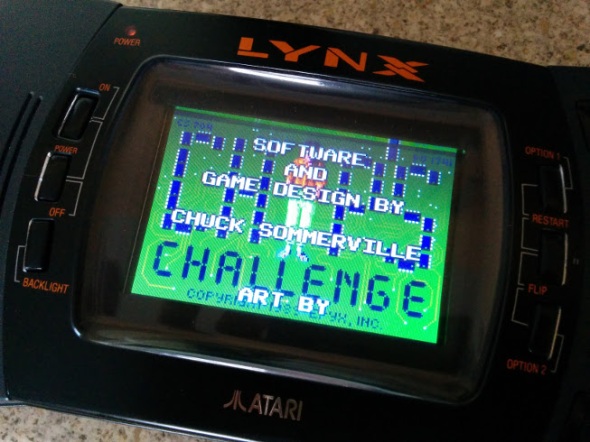
The Atari Lynx arrived on our shelves 27 years ago in the winter of 1989, only two months after Nintendo released the Gameboy and a year before the Sega’s colour handheld the GameGear saw light of day. Featuring the first backlit colour screen on any portable gaming device, the Lynx boasted accelerated 3D graphics.
Developed by former Amiga designers R, J Mical and Dave Needle, the ‘Handy Game’ came about after former Amiga manager David Morse approached them about designing a portable gaming system for Epyx. In 1989 faced with financial difficulties Epyx found itself partnered with Atari Inc, who agreed to handle production of the ‘Portable Colour Entertainment System” leaving Epyx to handle software development. Between 1989 and 1995 the Lynx was reported to have sold 3 million units world wide, but ultimately failed to beat the Gameboy even though technically superior in many ways. The Lynx is a fantastic system to add to any collection with 72 games released officially, varying from run of the mill to great titles like Chip’s Challange,

Lines the bane of any Lynx owner
Todds Adventures in SlimeWorld and California Games. However like most systems from this time its not without problems, the most predominant of which is screen failure. Usually this appears first as one or two lines running vertically or horizontally across the screen, more follow until the display is unusable. The root cause of this is the ageing ribbon cable that links the logic board to screen, over time becoming fragile and brittle. As it is an integrated part of the LCD display the only way in which you can cure the fault, is by swapping to screen for a new one. Which wasn’t a problem back when the Lynx was new, but in 2017 you might be faced with a problem, that is until now.
A Proper Solution

Stock screen looking less then great.
On AtariAge back in 2015 a user by the name of McWill came up with an interesting solution to solve the problem that had been plaguing so many Lynx owners. By developing his own custom display board he was able to replace the old failing screen with a modern LCD which not only offered superior picture quality but an optional VGA out. Unsurprisingly the board was an absolute success with Lynx owners far and wide, who finally had the means to repair their ailing consoles. Last year I was lucky enough to buy one of McWills kits, the board requires some self-assembly and a reasonable understanding of how to solder is needed. McWill does offer and installation service for those who don’t feel confident installing the kit by themselves. I was completely blown away with the image quality, which is ten times better then the original 90s LCD. The picture is sharp and the back light more linear, the full screen is now illuminated and gone is the incandescent tube glow of the original florescent light. The new screen uses modern EL technology which has come on leaps and bounds from when the Lynx was originally released. Ghosting and trailing has been significantly reduced, if not illuminated compared to the original 90s screen. If like me you’re accustomed to viewing your games on the old screen, seeing them for the first time on the new one can be a pleasant if not slightly shocking experience. I was honestly left wondering how the heck I’d managed for so many years without McWills screen mod.

McWills screen, there’s no denying the difference.
Priced at around 100 Euros the kit isn’t cheap however if you figure in the fact you’re getting a custom printed PCB and LCD its actually not bad value for money. The PCB is well made and laid out easy enough for even the budding amateur to follow. However the single sheet manual could have been written a little better as I stumbled to following it wiring to the TPR solder point. The wiring for this can depend on your model of console and what I didn’t know at the time was that I needed to close a jumper on the custom PCB. Labelled in small print as JMP1 in the printed manual its easy to miss and nowhere else is it referred to by this name. For instance here is an excerpt from the instructions.
‘For LYNX-II with chipset 1 (C104129-001) you have to use TPR (testpoint 27) only. For using TPR jumper is closed, for using RES jumper is open !’

Well laid out, McWills screen mod is relatively easy to install.
The instructions feature several diagrams with all the solder points labelled with names such as GRD, TPR, RES, CL2. I’m not entirely sure why the solder point is referred to as ‘Jumper’ and not JMP1, but it definitely threw me and I was left poking around the board until I consulted AtariAge. There I thankfully discovered I wasn’t alone and others were also being thrown by the same issue. This isn’t to say the manual is bad because it isn’t, only that it could probably benefit from a slight bit of revision to prevent others from getting stuck. Fortunately Marco aka McWill is a very helpful and friendly chap and after shooting him an email I was back on track.
Assembly will probably take you a couple of hours and I certainly advise taking your time and not trying to rush it. Some of the soldering can be fiddly, especially when it comes to attaching wires to the display pins on logic board. Using a fine tipped soldering iron is highly advisable. For wiring I used a good old trusty IDE cable, fine enough to fit on the small traces and flexible enough that i can manipulate the screen and board without working loose a connection. You will need to remove seven components from the main logical board before you can begin hooking in the new screen. You may also have carry out a 5 Volt check after removing the require components, so as to make sure the board isn’t exceeding 5.45 volt.

A fine tip is your best friend when soldering these pins
According the instruction the screen mod also has the ability to emulate the scan line effect of the original Lynx display, however I’ve been unable to get this to function. Not that I think I would really use it as the crisp look of the new display is pleasing enough and the games simply look amazing. If your Lynx is looking a little tired and you fancy giving it a face lift, I highly recommend getting one of McWill’s kits. While admittedly pricey, it will likely out live the life of the Lynx itself and beats replacing one old screen for another. As it’s only a matter of time before the ribbon cable degrades and your left looking for yet a replacement from a donor system.
Until next time, keep on geeking!
Back for 2017
Posted: February 12, 2017 Filed under: Atari, Macintosh, Raspberry Pi, Retro gaming, Uncategorized | Tags: apple, Atari, Lynx, picade, powerbook, raspberry pi 1 Comment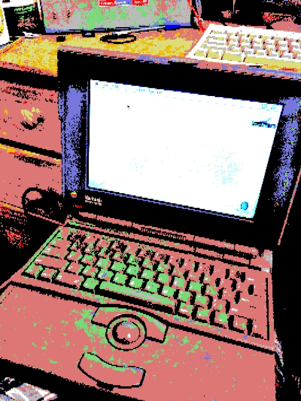
Hello dear reader! Did you miss us?
BMV is back for another year and I have a lot of fun articles I’d like to cover and maybe we can fit in a few interviews this year from people active in the community. I’m sorry the blog has been a bit quiet but I was away busily tinkering, working on my Atari Lynx video conversion, making an AmigaPi 1200 and several more USB tank mice for friends who wouldn’t stop pestering me for one after seeing the one I’d built I’ve also been playing with a Powerbook 180 and discovering the pitfalls of LCD tunnelling which the entire 100 series seems to suffer from.
Blasting away from 2016 is my Picade build which I finished just before Christmas, now in 2017 I put the finishing touches to the cabinet with some retro electric 80s art. Keep your eyes peeled as I’ll be offering up free cabinet decal art for anyone looking to deck out their Picade in proper 80s style!
Interview with Atari VCS 2600 PureVideo VEC Module Creators
Posted: February 26, 2015 Filed under: Atari | Tags: Atari, av mod, purevideo, RF modulator, six switcher, VCS 2600 Leave a comment
Last year I covered converting the VCS 2600 for composite video, replacing the aging RF output which many new televisions struggle with. The results were mixed, the picture was significantly better then it had been, but it still suffered from interference. Some months later I learned about the PureVideo VEC Module developed by Amibay users “Bluesbrothers” and “TC”. Two chaps who like me, were not happy with the picture quality of their 2600 and wanted to offer a better solution to fellow Atari enthusiasts.
Thus was born the PureVideo board, a professional looking, easy to install mod, compatible with the Six switcher woody to the Atari Junior. I bought one of these boards and have to say they are the MUST have mod for your VCS 2600. They make using a modern flat screen telly a painless experience!
I caught up with the pair last year and pick their brain about the PureVideo module and story behind it.
Q1. What spurred you to develop the Purevideo VEC?
Bas: An order of 25 units which became 50, didn’t think for one moment there would be a further order of 200 units including a major revision for NTSC compatibility.

The Purevideo VEC module
The challenge was set by Rob, and I went away to see just what we could cook up.
Rob: I’d been frustrated for quite some time that a drop in solution didn’t exist and that the hacks which were know about on the internet all seemed complicated, destructive to the PCB and none gave consistent results with every 2600 variant. I felt it was time for a proper consistent solution and so the hunt started for a proper engineer to tackle the problem.
I was always confident that this unit would sell in high numbers as long as we got it right which I believe we did though it took some effort to convince Bas that anyone would go out and buy this. I’m very pleased to say I have changed his perception on this completely and I don’t anticipate that the next order will last long once we put the product on general realise (we have kept it low key until now) and the revision to encompass NTSC compatibility should see a successful launch Stateside in August I hope
Q2. Were there any technical challenges in designing a board that not only worked with every 2600 console but also work with modern televisions?
Bas: There was no real challenge regarding the different 2600’s as long as the design stayed close to the TIA chip as this is a common device in all these different variants.
The brief I set myself however was simple;
- Minimal intrusion on the original console, i.e. invisible.
- No hard modifications to the PCB
- Simple drop in, plug and play concept.
- Blend in with the original pcb.
- Totally reversible.
- Consistent performance, no fine tuning.
- Allow RF operation to be easily available.
The above points were very important as some versions of the 2600 are quite rare and expensive…
Rob: For me the problem was finding someone who would actually follow through with the brief both on time and as closely as possible to the original brief only making changes for the better rather than to save costs or effort. It took several attempts to find someone who’d follow it through to the end before Bas got involved.
The module had to be easy to fit (for someone competent at soldering),… no complicated altering of resister ladders or cutting tracks.
No defacing of the machine itself – People like their toys but they also, on the whole, want a machine that hasn’t been butchered
The module had to give the same performance in every version of the 2600
Q3. BMV has delved in to modifying the VCS for composite in the past, how is the Purevideo VEC board different to the video hacks / mods that currently exist on the internet?
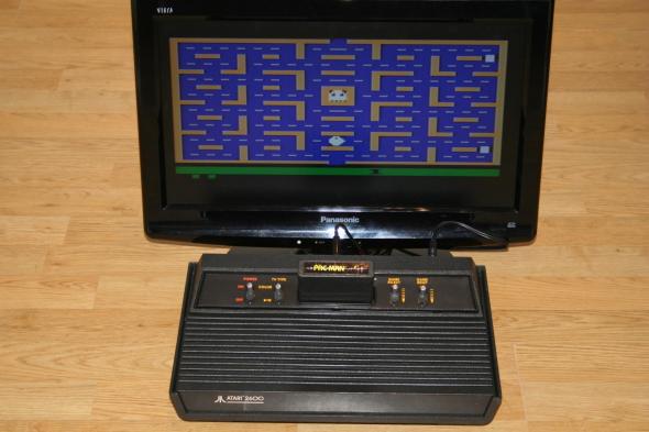
A 2600 running with PureVideo
Bas: The VEC2600 is an original solution, unique in the way it is fitted compared to internet hacks.
Careful and in depth calculations were made on paper first to ensure the correct luminance mix network and also to ensure marginal current had to be provided by the TIA..
The final Amplifier stage biasing was calculated to provide a linear output across the bandwidth and allow sufficient headroom so as not to clip the waveform, it also provides a slight lift to the black level to overcome the compression effect that LCD panels display in the darker region.
Even though the display on the oscilloscope was technically perfect, final manual tweaks were carried out to the biasing so that my eyes were happier than the scope.
It’s a testament to the amount of work that went into the design that when we trialled NTSC consoles we found no adjustment to the circuit was necessary at all.
Due to the method of install chosen it was decided to implement the module using surface mount technology, this has many advantages, mainly the noise performance remains very low and signal loss is minimised due to the short tracking and large Ground planes. The next revision actually uses even smaller surface mount components. The biggest benefit however is the module is manufactured easily offshore at a good cost ratio.
Rob: I’ll leave the tech explanation to Bas here but as Bas has said the solution needed looking at from a time served engineers point of view rather than one of an enthusiastic hobbyist and his knowledge in understanding the proper calculations gave us a solid starting point from which to begin rather than using a trial and error approach. It also needed to be driven to some extent by myself as regards the view point of the average consumer, it needed to be as simple as possible to implement whilst slick and professional in design.
Q4. How hard was it to take the idea in your head and turn it in to reality?
Rob: For my part the hardest thing was finding the right man to help me develop this and then (and he won’t mind me saying this and I often joke about it) feeding info in such a way as to make him believe he’s come up with the ideas.
One of the real bonuses to come out of this is a friendship and understanding another that has led us on to developing more stuff together and expect to see more products from the two of us in the near future
Q5. As we are on the subject of the Atari 2600, what is your favorite memory / game?
Bas: Indy 500 and Missile Command…
Rob: For me it’s Breakout because Pong/Breakout style games were just the thing back in 1980 which is my first memory of gaming and Space Invaders because where my Mum worked in a pub they had a Space Invaders machine and I was able to spend endless hours perfecting my alien blasting technique. Both games just remind me of being young and carefree. Happy times!
I’d like to thank Rob and Bas, aka Bluesbrothers and TC for participating in this interview and giving us all and insight in to this lovely piece of kit!

An example of RF vs Composite output.
E.T The Legend and the Facts
Posted: May 14, 2014 Filed under: Atari, Retro gaming, Uncategorized | Tags: Atari, e.t, gaming, landfill, video games Leave a comment
In 1982 Atari enlisted the talents of Howard Scott Warshaw to developed a game based on the film E.T the Extra-Terrestrial for the VCS 2600. The object of the game was to guide the alien through various screens and collect pieces of an interplanetary telephone, which eventually allows E.T to phone home.
Due to the popularity of the film, Atari anticipated the game to sell well. However when Atari finally secured the rights the produce the game, it had left Warshaw only five and a half weeks to develop the game in time for Christmas. The result was a commercial flop. Anticipated high sales, Atari produced 5 million copies of the game but only sold 3.5 million. A combination of returns and low sales would lead to the company netting a loss of $100 million., this would prove the beginning of the end for the once mighty video game giant.

Original photo of the site taken in 1983
E.T is regarded by most gamers as one of the worst games ever released. The failure of the game and the effects it had on Atari have led some to suggest it contributed to the games industry crash of 1983.
The Myth
In the years that followed, an urban myth developed around the fate that befell millions of unsold copies of the game as well as the thousands of copies that were returned. In 1983, a Mexican news paper based in Alamogordo, Mexico, reported a large number of trucks arriving in the city from an Atari storehouse in El Paso, Texas. The report went on to say, that the trucks had unloaded several trailers full of Atari games, consoles and peripherals to a landfill within the city, where they were crushed and subsequently buried.
Many dismissed the story as untrue, including E.T’s original developer Warshaw, who had the following to say on the subject:
“I’ve seen lots of evidence by hearsay and print but I’ve never really heard from any first hand participants and no one has ever produced a single cartridge from the burial site in over a quarter century.”
However for some gamers, Atari’s denial as well as that of some of it’s employees only fueled the spell of mystery around the fabled Atari treasure, which lay buried somewhere in Mexico awaiting discovery.
Since 1983 the E.T story has been told time and again, ironically making the worlds worst game in to one of the most talked about and known. Youtube is rife with video reviews of the game, the channel G4 even featured the it in an episode of “Code Monkeys”, in which the two main characters, Dave and Jerry are tasked with developing a game based on the movie E.T. True to reality the game they develop is terrible, resulting in an angry mob of gamers hunting for the developers responsible.
Digging up the truth
In 2013 the city council of Alamogordo granted permission to Canadian media company “Fuel Industries”, to search for the cache of unsold Atari games and other products which had been buried on the site over 30 years ago. The company organised the search in conjunction with Xbox Entertainment Studios, who plan on featuring the excavation in an exclusive documentary for Xbox One and Xbox 360, called “Atari: Game Over”.
On the 26th of April, 2014, the team of excavators armed with a JCB and bulldozers fell upon the landfill in Alamogordo. Extensive efforts had been taken by site organiser, Joe Lewandowski, to locate the site, once a local garbage contractor in Alamogordo. Interviewing truck drivers, landfill owners and local residents and listening to the stories of those who had witnessed the original 1983 dump as kids, and how they sneaked on to the site at night, coming away with handfuls of Atari cartridges. While the pressure was on during the dig, within hours of commencing the team had uncovered boxed copies of E.T, along with other games such as Defender, Centipede, Breakout and ironically Raiders of the Lost Ark. Hindered by strong winds and dust clouds, the team were only able to uncover a small fraction of the estimated 750,000 games buried on the site by James Heller, an Atari employee in 1983, who was tasked with the job of disposing of a warehouse of Atari products as quickly and cheaply as possible.
Present during the excavation were Howard Scott Warshaw original developer of Yars Revenge and the less successful E.T. As well as Joe Lewandowski screen writer and film director Zak Penn.
So there you have it folks, the mythical Atari burial site has been found, be mindful of anyone offering you a new boxed copy of E.T, as it may contain sand!
Keep on geeking!
Atari Six Switcher 2600 Video Modification
Posted: September 4, 2013 Filed under: Atari, Vintage Computers | Tags: 2600, Atari, atari av mod, atari composite, phono, RF modulator, VCS 2600 Leave a comment
Chances are if your visiting this site, you are the sort of person who still uses what people today refer to as “retro” hardware or as my girlfriend calls prefers to call it “tat”. Among all these precious artifacts is my console collection and the first proper console I ever owned: the famous Atari VCS 2600. The granddaddy of game consoles and one of the longest supported consoles in gaming history. The 2600 served to initiate a generation of gamers into the genre well in to the 80s, even after its hardware was considered dated. The Atari 2600 holds a special place in my heart, which is why in today’s blog, I will be telling you a story with a happy ending.
New Technology: Bane Of The Collector
So recently I purchased a new singing and dancing 27” wide screen IPS LCD television, retiring the 19” Sony CRT which up until recently had been fine for our needs, that is until HD movies came along and left me squinting as I watched the film Super8 on my now relatively tiny television screen. I was less than happy about shelling out for a new set, but the picture is pretty amazing, especially the colours. Maybe the tube was going on my Sony, but on the IPS screen my DVDs are really looking a lot better. As always there was a slight snag with this particular upgrade. The Sony had been perfect for hooking up any of the old consoles I had and the picture, albeit coming through the RF aerial, was still pretty clean. So imagine my horror when I hooked up the Atari to the new flat screen and was greeted with an amazingly fuzzy picture. Perhaps RF interference wasn’t as bad 20-30 years ago, but today in 2013, the picture was pretty dire. So that left me scratching my head, there had to be a way of improving the image quality. That’s when it hit me, what about composite? The Wii was hooked up via composite and the picture was pretty good, so why could the Atari not do the same?
The Internet: The Fountain Of Knowledge.
I spent the best part of the evening and the next day looking online for adaptations for the Atari 2600 that would convert it from RF to composite. Several of the guides, while promising, also came with a warning to the would be modder. Not all 2600’s took to modification the same way. Sometimes you would get a good picture or the colours might be out, worse you might not get a picture at all. This really didn’t fill me full of confidence while I researched the mod. Even my favorite web show Ben Hack had a spin on the video mod, his included two 1k pots for adjusting the picture if the colours were out. Personally I wasn’t bothered too much by the colour, I mean seriously. I had been putting up with RF for years, the benefits of a half decent picture and not having the tune the set in where more then good enough for me. After all this is an Atari 2600 we where talking about. How sharp do you need those pixels? A square blob is still a square blob even in high def!
In the end I settled on a mod I found here http://retro.mmgn.com/Nintendo-64/Forums/Atari-2600-AV-Mod
Credit goes to Brighty83 for posting this originally,
To do this mod you need:
Shopping List:
2.2k Resister
3.3k Resister
2N3904 Transistor
Small Circuit Bread Board
Twin Phono leads (3 meters)
Wire for hooking up your components.
‘Optional’ Additional equipment
Soldering Iron, fine or normal tip will do
Multimeter
Wire clippers
Heat shrink for your wiring
 Attention: Do not attempt this modification unless you are comfortable using a soldering iron and have a reasonable grasp of electronics. Neither myself nor the original author of this hack is responsible if your Atari comes alive and tries taking over the world or worse stops working all together!
Okay so that is the warning out of the way, lets get busy hacking!
For me this was a really easy, straight forward hack that ended with a good result. The picture quality might not be amazing on Ms. Pacman, but on most of my other games it is pretty damn sweet. Unlike other mods that allow you to adjust them on the fly, this mod gives you a generally good picture across the board without altering the aesthetic look of your Atari console. This was the most important factor for me, all I wanted was to swap my 5-6 meter long RF cable with a composite.
First of all you will want to build the circuit board that will eventually go inside your machine. For my installation of the hack, I altered the design, as I did not want a set of phono sockets on the rear of my Atari 2600. Instead I wired a 3mtr phono lead directly to the circuit board. I drew enough of the lead inside the console through the hole for the RF lead and looped a knot in the phono cable. This meant if the cable was pulled or snagged, it would not be ripped out of the console, damaging components. Alternatively you could use hot glue to secure the cable.
Below is the diagram for the circuit, note this is how I have it built inside my Atari. If you want phono connectors on the rear of your machine, you will need to alter the wiring slightly. It is up to you if you wish to connect wires to the board yet or connect them first to the points on the Atari. I cut 5 wires roughly 10” in length and attached them to the bread board.

Using: Black = Ground, White = +5v, Yellow = Audio (tip: Fit your transistor so that the emitter is where the letter ‘E’ is shown on the diagram.
I used an additional brown wire to route the ground to an isolated area of the bread board so that I could ground the exterior audio, as pictured below.

Once you have put the circuit together you will need to take apart your 2600 and begin tapping in to contacts on the motherboard. Flip the console over and remove the six screws indicated in the image.

Once you have the lid removed, disconnect the cable connected to the controller board, this is the board with all the switches. With the cable disconnected, unscrew the two remaining screws that are holding the board in place. Gently lift the board out and place it to one side.

Returning to the console, you should now be left with the cartridge slot and a large metal housing. Flip the Atari over and remove the two screws as shown. The motherboard should now be free of the plastic base. Lift it out and flip it over, removing the screws indicated.

With the motherboard exposed, you need to tap into the audio line of your 2600. Solder one of the 10” red wires to the pin indicated in the photo.
Replace the metal back plate, threading your red wire through one of the holes and screw the unit back together. Place it back on to the plastic base of the console and screw it in to place, making sure you use the screws with the spacers!

Now that’s one down, next on to the video. Get hold of your controller board and flip it over so you can see all the pins, try and locate the RF module, use the photo as a guide. Unless you have removed you RF module, you need to solder your wires on to the rear pins of the RF module, as shown in the photo.

Pin 1 – Black wire = Ground
Pin 3 – White wire = +5v
Pin 4 – Red wire = Video
Before you begin work on the controller board, I would like to give you a little advice. Your 2600 is roughly 25+ years old, which means the traces on the PCB are fragile. So try to be gentle with your soldering iron, don’t expose the PCB to too much heat. If possible use a fine tip, which will focus your work and make for a tidy job. As you see in the photo above, my attempt isn’t great to look at, but it does work. Will teach me to use a worn tip on my soldering iron. Fortunately this mod unlike some others, does not require you to solder directly to the TIA chip. Instead we are tapping in to the necessary lines just before they feed in to the RF modulator.
Some guides recommend that you remove the RF module, this I leave entirely up to you. I left mine connected as it has been sitting there for the best part of 30 years and it seems a shame to remove it. As far as I’m aware leaving it installed does not effect our modification, but installing the mod will disable the RF module from functioning.
With your wires now connected to the board, carefully place the board back inside the 2600 bottom case, fixing it down with the two screws you removed earlier. Reconnect the cable to the top of the board, reconnecting the logic board and controller board back together.
Unless you did so already, solder the wires coming from the controller board to the circuit we built. Once you have done this, you should be good to go.
Before applying power to the console, if you have a multimeter and know how to use it, I highly recommend you do a line test on all your soldering points. Make sure there are no crossed lines on your bread board circuit. If it all checks out okay, hook the console up to your TV and try playing a game.
Hopefully it all worked and you have an Atari now working on composite. Secure all your wiring, making the inside look tidy before finally screwing the lid back in place.
Now pat yourself on the back, well done!
