
MegaPi Zero
Posted: May 24, 2018 Filed under: Linux, Raspberry Pi, Retro gaming | Tags: emulationstation, megadrive, pi zero, raspberry pi, raspbian, rpi, Sega Leave a comment
The MegaPi
Not long ago I bought myself a NESpi and was telling a friend about it. She went on to ask me if there was a Sega equivalent, as her brother was an avid Sega fan growing up. Sadly I had to tell her there wasn’t but that added, that building such a console wouldn’t be that difficult, me and my big mouth. Thus I found myself with a new project on the drawing board, added to all the other projects I was tinkering with. When will I learn?
Having built the NESpi and my Picade, I knew EmulationStation could easily accommodate my needs. Not only can it emulate the MegaDrive, but the Master System, GameGear and SegaCD as well. The only real question was what platform I would use for all the grunt work. A Pi3 seemed a little overkill, true it would handle anything thrown at it, but it also hiked up the cost of the build and I was trying to keep to a budget. I might have been able to pick up a second hand Pi2b, however they seem to sell close the what they cost new. I didn’t want to go down the clone route as support isn’t as good, so that left me with one option, the Pi Zero. I’d never tried using a Zero for playing games, messing about with electronics yes, but gaming just seemed a little to demanding for BCM2835 processor. However if you read up on the Zero, for such a tiny board, you realize its actually quite powerful. Clock at 1Ghz, the CPU is approximately 40 percent faster than the same chip inside the original RaspberryPi. Tests have shown the Zero operates roughly four times faster then the original Pi. While I was never going to see Pi2 performance, it would hopefully be enough to emulate the MegaDrive. It seems a little crazy that a 1ghz 32bit processor shouldn’t be capable pf running 30 year old software, but we have to keep in mind, that the Zero is being call upon to accurately emulate a whole console. Translating sound, display, input on the fly, into something close to the real thing.
Building
From the beginning my intention was to alter the MegaDrive very little, in fact I wanted to replicate the consoles original functions. Allowing the Power and Reset buttons to work pretty much in the same way they had before. I was able to make this possible using Pimoroni’s on/off shim, this tiny board sits atop the Pi’s GPIO header and allows you to safely shutdown the computer with the touch of a button. It also comes with through holes, allowing you to solder your own button to the board. The shim is pretty versatile, you can either use the included header block or solder the shim directly to the GPIO header, thus freeing up the GPIO pins if say you wanted to use another HAT, like a PHAT DAC. Once installed, for the shim to function you must plug power in to it directly and not in to Raspberry Pi. That way power is being fed through the shim in to the Pi via the GPIO header, putting the shim in control of feeding power to the Pi. The added bonus to all of this, is that your bypassing the Pi’s annoying poly fuses.
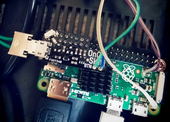
With the power sorted out, the next step was the Reset button. The Zero, like other Pi’s comes with a pair of through holes labeled ‘RUN’. If you short them, the Pi’s CPU will halt what it’s doing and reset the system. Ordinarily this isn’t something I would recommend doing regularly, as you run the risk of corrupting your SD card. However, if your running a Pi and for what ever reason it locks up. If your only input devices are two joypads, a reset button might just be what you need to get back on track. This was first time I’d ever wired up a reset button on the Pi and later was thankful I had, as on one or two occasions EmulationStation locked up because I’d done something stupid.
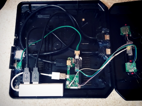
Out of the box, the Zero comes with only a single micro USB port, which isn’t much good if you want a two player game of GoldenAxe. To work around this problem, I used a compact USB hub, specifically suited for the Zero as it came with molded micro USB connector and not a full size USB plug. I then used a set of cables to extend two USB ports to the front of the console, where the joystick ports had once been. I also made a custom power lead, one end going to the rear of the console as a dedicated power socket and the other going in to the on/off shim. Always use thick gauge wire when extending the Pi’s power socket as it only take a little voltage drop for the dreaded ‘undervolts’ icon to appear in the top right hand corner of your screen.

For the rear panel of the MegaPi, I designed a custom I/O panel to replace the Megadrives existing RF and Power Jack with micro USB and HDMI. After cutting out the existing panel, I hot glued the laser cut acrylic panel in place, along with the cables coming from the Zero. I applied a copious amount of glue to both sockets, especially the HDMI port as I found it a little tight when I was hooking up my TV.
Press My Buttons
I’ve already mentioned how I was able to get functional Power and Reset, but getting both to work with the cases existing buttons was a challenge unto itself. First I began with two tall 6mm tall micro switches, which I soldered to strip board and later trimmed to fit the area under both red buttons on the case. It took a little trial and error, trimming the height of both micro switched until they worked properly with the buttons. When I had both working to my satisfaction, I used my trusty glue gun to affix them to the underside of the top lid. Glue guns are by far, the makers best friend!
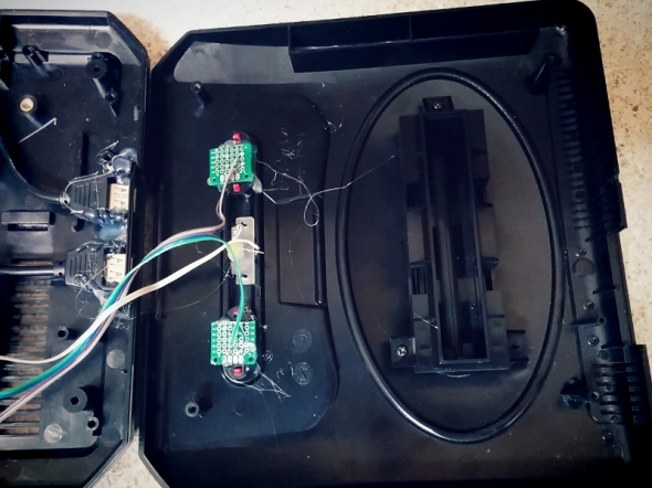
With the both switches in situ, all that was left to do was connect them up to the pi itself. A quick test, proved both worked as desired and so the next task was setting up the software.
EmulationStation
Without a doubt, building the Megapi would have been a very different story if it were not for EmulationStation. Setup and configuration of this software has been made very simple, allowing even the most inexperienced to follow it. Configuring the Sega style USB controllers I’d bought was a little fiddly but trial and error eventually prevailed and I had both working as desired. I was even able to setup a custom loading screen and Sega themed booting screen. The first time I came to try out a game, I was really surprised by the performance. The Zero handled most games I threw at it, struggling only once or twice, I doubt very much it could handle any of the 32x or SegaCD titles. But as a bog standard Megadrive it copes pretty well, better then a £5 computer really ought to. But it just goes to show what good value the Zero is and what it possible with such a cheap, tiny computer. I’m really glad the foundation developed the Zero, with the increasing speed of the larger Pi3b and now 3b+, it stands as an affordable foot in the door. Had the Zero not be around, I probably would have tried to buy a cheap second hand Pi2. For the simple fact that the Pi3 was too expensive and powerful for my needs. That being said, I’m not even certain the larger Pi form factor would fit inside the MegaDrive II case.
Conclusion
This was a fun project and not one I would have made had it not been for my friend asking. Truth be told, once built, I grew really attached to it and was sad when it came time to hand it over for my friend to give her brother. From what I gather though, he really loved his birthday present. Hopefully he’s reliving his childhood, maybe even having a mate over for a few beers a game of sensible soccer or Sonic and Tails.
The on/off shim is available via the Pimoroni website at
Building A Portable Pi
Posted: April 11, 2017 Filed under: Linux, Raspberry Pi, Vintage Computers | Tags: adafruit, portable pi, powerboost 1000c, raspbian, rpi Leave a comment
For a long time I’d thought about creating a portable Pi but wasn’t really certain where to begin, so for a long time it remained just an idea rolling around in my head. After building the 600Pi I developed a greater understanding of what was involved fitting a Raspberry Pi inside a custom enclosure, such as extending the USB, HDMI and Ethernet from the tiny Pi and how to power the motherboard directly, bypassing the traditional on board USB port. The 600Pi really opened my eyes and taught me a great deal, not just about wiring, but also about hacking the Pi’s various features. A month or so after finishing that project a friend gifted me a box full of random bits, because if there’s one thing friends know about me, it’s that I love boxes filled with parts. Inside was an assortment of USB cables, fans and a RPI2 B fitted in a custom acrylic case. What caught my attention about the Pi specifically was the 3.5″ LCD panel that was attached to it, as soon I saw the screen the cogs in my head begun to whirr. Well suited for a portable pi project, it was just a matter of me drafting up a design.
A few weeks after receiving my box of goodies I was clearing out a bunch of old stuff from under the bed when I found an old project box lurking under the mattress. A left over from when I was designing my Nomad desktop system, it was just the right size for a portable retro computer, not to mention it already looked kind of old. Originally there had been two but I’d hacked one up for the Nomad, only to find it had very little air flow and caused the mini ITX board to overheat. However, unlike the larger mini ITX board, the Pi not only had a smaller foot print but would never reach the operating temperatures of an Intel Duo processor.  At first I wasn’t certain the LCD panel would fit in the front of the case, but pairing the two together proved it would be a snug fit.
Admittedly, building a portable Pi isn’t anything new, people have been putting them inside all manner of things ranging from teddy bears, tea pots, remote control drones and even coat pockets! You can find Pi powered laptops, C64s, Spectrums and even 3D printed Gameboys like the Pi-GIRRL, however my goal was to build a portable computer with a distinctive 80s retro feel, bet you didn’t see that coming did ya! Using a case originally intended for my Nomad desktop, I decided to call my new portable the ‘Nomad SX/Pi’ in homage to my earlier project and also the Commodore 64SX portable computer, a machine I was drawing much inspiration from.
Design
 It’s probably no surprise the SX64, Keypro, Osborne and even the TRS80 M100 inspired the design of my project. All are note worthy machines, successful back in their day with a dedicated group of followers even now. Their appearance resonates a specific time in computer history and it was this aesthetic styling that I wanted the Nomad SX to imitate. Measuring 257 x 190 x 85mm the case had ample space for the Raspberry Pi, however the 3.5″ LCD was another matter. It was almost as tall as the case with only 10mm clearance between the top and bottom lid. As I had done with the 600Pi before, I extended the Pi’s ports to the front and rear panels of the case. Included in the rear panel was:
- 1 x USB
- 1 x RS232
- 1 x Ethernet Port (Rj45)

Front panel with USB and audio
- 1 x MiniUSB (Power Input)
For the front I extended the Pi’s audio jack and another of the USB ports along with the Pi’s power and activity lights. Having only recently upgraded the 600Pi with a new Pi3, it meant I had spare Pi2 board with the on board LEDs already modded for extending to the front panel. The reason I didn’t extend all the USB ports was because I needed two of them for Bluetooth and Wifi.
After making a couple of rough sketches I sat down, using Inkscape to draw up the vectors I would need to cut the front and rear panels out of acrylic. Previously I’d used an old version of Adobe illustrator, but a couple of my friends kept insisting I gave Inkscape another shot, even though I’d struggled with it the first time round. My initial impression of Inkscape was that it was powerful but far less intuitive then Illustrator,, but it does have one thing working in its favour. Unlike Illustrator its an open source freeware application, meaning it doesn’t cost you a penny to use.

Better view of the rear panel
Installing it on the Nomad, I spent the evening drawing the panels using the sketches I’d made earlier. After a some what slow start, I actually found Inkscape to be pretty straight forward and not as complicated as first thought. In fact once your in the Inkscape zone it’s actually a pretty powerful application. Available for Linux, Mac OS and Windows, I highly recommend checking it out and did I mention its available for the Raspberry Pi?
Input / Output
One part of the case that was causing me a headache was the keyboard, originally I’d wondered if I couldn’t buy a small keyboard and hinge it to the front of the case similar to the Keypro or attach it with Velcro. However that meant finding a keyboard with the exact same dimensions as the front panel which was highly unlikely. Unlike large manufacturers that can fabricate custom parts, I was limited to finding off the shelf parts to get the job done. After a lot of searching on eBay, I found a wireless keyboard and waited patiently for it to arrive from China. Almost as soon as I unboxed, I realised it was rubbish,

3.5″ of retro goodness
surprise, surprise. The touch sensitive panel was smaller then I’d expected and pretty useless for typing anything. That is unless you wanted to finger type everything, which as I found resulted in almost inebriated sentences of typo ridden nonsense. So it was back to the drawing board and searching once more online for a suitable keyboard, a search that had thus far been less than successful. It turned out I hadn’t needed to worry as only a couple of days after my disappointing eBay purchase, my prayers were answered. While picking the other half up from work, I was telling her about the problems I’d been having when suddenly she revealed her work stocked several bluetooth keyboards on their online shop. A quick trip across

2.4Ghz wireless and sadly disappointing
the warehouse floor and I was staring face to face with an ultra slim bluetooth keyboard and not just that, it was narrow! Talk about irony, I’d spent the best part of a month looking for one under 250mm wide and all the while Pimoroni had exactly what I’d wanted on their website and it was 240mm wide, 10mm shorter then the case I was using.
With the issue of the keyboard finally behind me I was able to redesign the front and rear panels to accommodate the new BT keyboard. Originally I’d planned for the little touch panel keyboard to slide inside a slot in the front, but as that wasn’t happening now, I had to find room to accommodate the larger 240mm x 90x 14.5mm keyboard. Barely 10mm narrower then the case, I had to come up with a smart way of stowing it away. Strapping it to the outside would undoubtedly expose it to unwanted knocks which would likely wear it out in no time at all. Don’t ask where the idea came from but scribbling on a piece of paper I found myself staring at a sketch of the rear panel with a narrow slot for inserting the keyboard inside. Refining the design further resulted with a shelf inside the portable for the keyboard to rest on when it wasn’t in use, I also designed a blanking plate to screwed in place over the slot to keep the keyboard from sliding out while the computer was being transported. While it wasn’t like anything I’d seen on the Z80 portables I’d been using for reference, it certainly worked and solved the problem of where to put the keyboard.

Rear panel went through several revisions before it was right
As there was no need for a slot in the front panel I redesigned it, turning it in to a sliding door and IO plate for the audio jack and USB port. Taking advantage of the reclaimed space I also included a badge to sit above the IO panel which read “Nomad Pi/SX – Portable Micro Computer”. It seemed fitting given the size of the Raspberry Pi computer hiding inside the case.
Bluetooth Woes
Setting up an Ultra Slim keyboard on the RPi wasn’t as smooth sailing as I’d been expecting and required some work before it was up and running properly. I also encountered an annoying problem where the top row of F keys weren’t recognised by Linux, even asking the guys at Pimoroni and on the RPi forum yielded no solution. Two months after finishing the portable Pi I was at a friends sampling a pint of homebrew beer when the answer came to me. I don’t completely recall what led to the discovery (how strong was that beer?), but long story short Linux was mistaking the ultra slim keyboard for a BT Apple keyboard. It turns out these are known for having issues with Linux and there’s even a wiki page covering it, see this link for details.
LCD Screen

Adafruit Powerboost 1000C, a fantastic little PCB
For the Pi’s composite video jack I used a 3.5mm jack cable, splitting the left, right and video lines. I hooked the video feed up to the LCD panel and the audio channels to the audio socket attached to the front panel. At some point I plan on installing internal sound but that will be a work in progress. When I discovered the PI / LCD combo, I originally wrote down the wiring so that I’d know how to connect it back up. Like any scrap of paper it inevitably went missing and not knowing the model of the screen or where my friend had bought it, I was left in a bit of a pickle. How was I ever going to figure out the wiring? Luckily for me I’m on the Sheffield Hackerspace mailing list and after posting up a request for help, I soon had a link providing me with all the info I needed to connect up my tiny screen. Words honestly can’t do justice for how grateful I was when the tiny LCD lit up for the first time, so a big thank you to the guys at the Sheffield Hackerspace.
Because I was planning primarily to use the terminal and not x.org to operate the Pi, I found the text on a 3.5″ screen a little difficult to read. Online I found several guides showing ways to increase the text size within the Linux console, and I also read up on altering the screen resolution which was running in its default res of 1080p (I guess). Either way it was causing the 3.5″ screen to flicker at a headache inducing rate. Fortunately the config.txt is pretty flexible and allows you to tailor a lot of the Pi’s settings to suit your needs, which is great for anyone trying to use a 3.5″ screen with their Pi via composite out.
Tackling Small Screens
Having only ever hooked a Raspberry Pi up to a VGA monitor, I’d little experience configuring the config.txt file to display on a small screen. Especially one using composite output instead of HDMI. Fortunately there’s plenty of information available online to walk you through setting up the config file and a bit of trial and error I was able to get it working. By setting the screen to 480×320, I was able to eliminate almost all of the screen flicker present while the screen was running in high resolution. Additonally making it much easier to read text, as even in 800×600 it was incredibly small. Though lowering the resolution made the text more legible it still  wasn’t suitable for using over an extended period. This led me to looking at changing the Terminal itself and how I could configure it to display differently on the Pi Portable. Fortunately you can alter the Terminal using the following command
"sudo dpkg-recofigure console-setup"
Going through the prompts I set the terminal to use the ‘TerminusBold’ font at a size of 11×22 as this was easy to read and didn’t take up to much room on the screen. It took me a while to figure all this out and I went through several computations of the various fonts and sizes before I found the right one. While doing a little research for this article I discovered one of the machines I’d used for inspiration has a larger screen than I’d first assumed. The Osborne-1 is often cited as the first portable personal computer and it along with the SX64 were machines I used as examples while designing the Nomad SX. As it turns out the 1981 Osborne-1 came with a 5″ screen capable of a mind blowing 128×32 character display. Which is impressive compared to the 11×22 display on the Nomad, if I ever make another portable I’ll be sure to make the screen bigger!
Not A Leg To Stand On
After getting the machine together I realised the viewing angle wasn’t exactly ideal. In fact to read the screen I had to prop a book under the case. I’d not really envisioned using a stand like the SX64,  but as it transpired I actually really needed one. If I’d stopped to think back about all those old Z80 machines, a large number of them did come with a kickstand of some sort. Designing a set of legs I got them laser cut from acrylic and fitted to the sides of the case. I used nylon lock nuts so that I could tighten the screw enough so the legs were stiff to move, but with the advantage that lock nuts wouldn’t work themselves loose. The downside to using acrylic is that under certain circumstances it can be a fragile material and exposed to stress will sometimes shatter or crack. As the legs would be in regular use, I wasn’t certain how long the acrylic would last. With that knowledge ever present in my mind, I spent a lot of time trying to think of an alternate solution. Eventually I settled upon 3D printing and fabricating a single piece carry handle, as you can see in the picture the prototype came out pretty good.
Being Portable Means Being Portable

Part of this project was to make a portable micro computer that I could take with me wherever I liked. This ultimately meant using a battery, something I’d never done with a Pi before. So once I had the system working and all of the internal wiring finished, I began looking at batteries and also charging circuits. Obviously because of the screen, bluetooth & wifi dongles, I would need a pretty substantial battery to power everything. It was around this time that Pimoroni began stocking batteries via their online store. I also noticed they stocked the Adafruit Powerboost 1000C, a small 5v 1Amp board that doubled as a battery charger. Choosing one of their 4400mAh batteries and the power boost, I set about modifying the internal wiring of the Pi Portable. Instead of the power going directly to the Pi it would have to go via the Powerboost first, so that the internal battery could be charged.
I’ve seldom bought anything from Adafruit aside from perhaps a micro usb socket but I have to say the Powerboost is a fantastic bit of kit and really does credit to Adafruit. Not only was it straight forward and simple to wire up but I found the additional

A sneak peak inside, yes its crammed.
power switch an especially nice feature, one that I hadn’t been aware of at the time of purchasing. It was certainly a lot better than pulling the plug, as is the normal way to turn off your Pi after shutting it down. As the back panel was in need of revision due to some stress cracks showing, I added an additional hole for a switch, which complimented the rear panel really well, giving it a very professional look. Combined with all the accessories, the Pi portable draws approximately 740Mah, which means I should get nearly 5 hours out of the 4400 battery. I’ve yet to actually bench test the Pi portable to find out if those figures are anywhere near accurate, but even if the system can manage 2 hours, I will be happy and consider the upgrade a success.
Closing Thoughts
While it might not be as sleek or as compact as many other portable Raspberry Pi builds. I’ve taken the Nomad Pi/sx to several retro events and had nothing but positive feedback. Many remember using machines like the SX64 and Osborne back in the day and instantly latch on to the similarities. Loading up Dizzy via the C64 emulator never fails to generate a smile. But if I’m honest, I always end up playing Outrun or Stuntcar racer!
This has been a funny old build but one I’ll definitely remember if not for the fact that I do use the computer on and off when I need a distraction free typing environment.

Raspberry Pi 2 Model B
Posted: February 18, 2015 Filed under: Linux, Raspberry Pi | Tags: Arm7, linux, Model B, Raspberry Pi 2, raspbian Leave a comment

img src: http://www.muycomputer.com
Unless you have been hiding underneath a rock these past few months, you will likely have heard about the last release from the British based Raspberry Pi Foundation. Who last month unveiled the latest edition to their line of micro computers, the Raspberry Pi 2 – Model B. The new model is an impressive step up from the original model B and B+, both of which utilise a single 700mhz core Arm11 processor and 512MB of internal memory. With 1GB of ram, the Pi 2’s new quad-core 900Mhz Arm7 BCM2836 processor was designed by Broadcom specifically for the new Raspberry Pi. The Pi 2 Model B is substantially faster than anything the foundation has released thus far. The upgrade now pushes the Pi in to the same league as boards such as the O-Droid and other multi core boards suited for hackers and gamer’s looking to run resource heavy tasks. Such as playing hi-definition video or Mame arcade emulators.
In a previous article I wrote about my frustration when I tried to get Mame to work right on my Model B. With the new Pi 2 spec, such headaches will be a thing of the past. In fact the release of the Pi 2 Model B in my opinion is a real game changer. Up until now, I was rather disappointed with the Raspberry Pi, maybe because I wasn’t using it for the purpose it was intended for.
I’m from a generation that grew up with Spectrum’s, Commodore Amiga’s and Duran Duran on the radio. When I see a tiny micro computer, my first thoughts are not whether I can fit an LED or robotic arm to it. I’m more bothered about what games I can play on it, if it will emulate a BBC micro and whether I can use it for email and light surfing. Later down the road I look at inputting programs and learning how to make games using Python or what ever passes as the modern-day equivalent of BASIC. I don’t know why I’m saying my generation, as I’m sure any ten year old today would want to do the same as I did at that age. Not just play games, but want to tinker with the code to get an extra life or skip a level by hacking the game. That was half of the fun of having a micro computer and having games written in an easy language like BASIC.
New Potential
The Pi 2 Model B is now powerful enough to realistically perform as a cheap home computer. While you might not be able to watch BBC Iplayer or Netflix, you can use it for other things such as:
Wordprocessing
Graphic editing
Music editing
Playing games
Surfing online
Receiving email
I know some of you will be reading this and saying that these are all things the Model B could do already. To an extent I would agree with you, but my experience was that doing any of the above listed tasks caused my original Model B to have a small panic attack. After which it would sit on my desk blinking with the CPU at 100%, getting no where fast. I realise the original Raspberry Pi was meant to be a computer for schools, it was never intended to be a desktop computer. So to compare it to our laptops or towered PC’s is to be unfair on tiny micro, as your average home computer has many times the power and memory of the model B 700Mhz Arm11 processor. However I would argue that if the computer was never meant to surf the internet, why then include a web browser with the operating system? Such questions can spark heated discussions online, so I’ll simply say that the only person who can tell us, is the person who organised the Raspbian distro to begin with.
Utilising four 900Mhz cores and 1GB of 450Mhz RAM , the new Model B is roughly six times faster than the previous model and give a lot of grunt for a £30 pocket size computer. The Raspberry Pi might have started its life in the class room, but it could now potentially find itself in kids bedrooms around the world, just like the Spectrum and C64’s of the 80’s. Perhaps parents wanting to get a computer for their children but worried about it getting broken, will see the Raspberry Pi as an affordable alternative. Time will only tell if this happens, I certainly hope it does as many of those kids from the 80’s and 90’s grew up to be the game programmers of today. Working on games for the 3DS, Xbox One and the Sony Playstation 4. Many of them will no doubt be able trace their computer interests back to the days of getting home from school and playing on their Amiga, C64 or BBC Micro. Wouldn’t it be nice, if in 10-15 years time a new generation could look back, and trace their programming roots to the day their parents brought home a new shiny Raspberry Pi 2?
Closing thoughts
It’s still early days here at ByteMyVdu, but the general feeling is that the Raspberry Pi 2 is a step in the right direction, if not a little overdue. It is a pity that the Foundation didn’t bring this out instead of the B+, which is more or less a facelift of the B. I had intended to buy a B+ but with Christmas close at hand I held off until the new year. I suppose I should be grateful I did, otherwise I can imagine this new release would leave me a little annoyed. Having spent £30 on a new computer, the last thing anyone would expect to see is a new and vastly superior model released 6 months later. I only hope there is a reasonable explanation for the foundation releasing the B+ and Pi 2 B so close on its heels. I honestly can’t imagine Apple or HP doing this with an Ipad or a laptop, as it might damage customer confidence. Computer technology has always resided in the fast when it comes to progress, however most companies leave a reasonable amount of time between product releases. Which is why I was understandable surprised to hear about the Pi 2 B being released. It doesn’t seem that long ago that the foundation released the B+. Regardless of the reasons, the Pi 2 Model B is here and I’m certain people are going to like it. After using mine for several days I can honestly say I’m impressed, it performs how I’d hoped my original model B would have when I first bought it. I suppose a lot of this is down to the custom BCM2836 SoC which Broadcom made specifically for the new Pi 2. I’m really looking forward to seeing what this new computer can do and what fun things I can do with it, aside from write blog entries. This is the first time I’ve been able to write an article for ByteMyVdu on a Raspberry Pi and not only write it, but then upload it to WordPress while still using the Pi. In the past trying to log in to WordPress would kill my Model B to the point that I’d have to unplug and plug it back it in just to resuscitate it. Actually being able to log in to the site and edit my blog is simply unheard of! I have to say I’m thoroughly chuffed with the new Model B and look forward to the coming months. I wonder if I can interface my TRS80 Model 100 with it using Minicom? Let the tinkering commence!!
Till next time, keep on geeking!
“Raspberry Pi Part II”
Posted: September 20, 2012 Filed under: Linux, Raspberry Pi | Tags: Debian 6.0, linux, pcb, raspberry pi, raspbian, setting up raspberry pi, setup guide for raspberry pi 2 Comments
So last week a friend asked if I’d be interested in looking at Mame on the Raspberry Pi. As I didn’t yet have one, he graciously lent me one as he is already busy making Pibows, a custom acrylic case for the Pi PCB, he simply doesn’t have the time to spare looking at getting Mame up and running.
Never one for turning down a challenge nor the opportunity to play around with a Raspberry Pi. I began digging around on the net, finding out as much as I could about running arcade games through Mame on the Raspberry Pi, not to mention how to set the darn thing up. I had read that the primary OS was Linux, a Debian distribution to be precise called Raspbian. Perhaps playing around with Lubuntu on the Nomad for all those months was going to pay off.
Things You Might Need

Left – Mini USB, Right – Micro USB – Becoming the standard for many devices.
When I was handed the Raspberry Pi, it came in a tiny white box. Inside you got, the PCB in an antistatic bag and a piece of paper telling you that your device meets all the right EU regulations. To keep costs down, Pi’s are not sold with any accessories, the idea being you buy them separately. There’s also a good chance you own some of the parts already.
The Pi is powered via a standard 5 volt – 1Amp micro USB, which is used on many modern mobile phone chargers. As for video, you can choose to go old school analog and use the composite RCA port (phono), just like back in the day with the ZX Spectrum and C64.You will need a phono to phono cable or if you want to get techie, a male to male RCA cable for this. The picture isn’t amazing and on a CRT it’s headache inducing. An LCD does give better results, if a little blurry.
Alternatively you can use the more modern HDMI port, which will give a much better digital picture and is compatible with most modern flat panel televisions. If you own a flashy new telly, you might have a spare HDMI cable laying around. If not you will need to decide which method of display your going to use.
For storage you will need to buy a class 4, 4GB SD memory card or bigger. The Pi foundation advise against using none branded memory cards, such as the cheap one’s you find on ebay. The Pi needs a good quality card for the access speeds. Otherwise you might encounter problems running your OS. For Sound, any set of speakers should work fine with the Pi. Alternatively a 3.5mm audio jack to phono cable should allow you sound through you TV.

Not Feeling The HDMI Vibe
If like me, you don’t own anything with HDMI, you will be stuck with using composite. Unless you buy a HDMI to VGA converter, which will allow you to hook the Pi up to any PC VGA monitor. I found one on ebay for £8, it’s yet to arrive in the post but with some luck it will make the Pi more useful.
- Going Analog
First thing I have to say is don’t use the Pi on a CRT television for any length of time through composite. If you’re using the terminal your might be fine. However myself and a friend found booting into Raspbian to be almost unbearable. The picture was extremely flickery, like Amiga 1200 Pal Hires Laced flickery! Unless you like eye strain and headaches, I strong advise against using this setup for anything other then running commands via the terminal.
- Composite to Scart
You might find on ebay that some sellers are offering a scart cable for the Pi, this is simply a composite output to through the Televisions scart connector, it does not alter the picture from composite.
- Analog & LCD TV
This is possibly the only good way to use the composite display. LCDs don’t suffer with flicker like CRTs. While the image might be a little blurred, it’s a lot less harmful on your eye’s then the alternative. Luckily most LCD televisions come with composite for hooking up such things as consoles, video camera’s ect. BMV Recommends this method to those geeks on a budget, who cant afford a new TV or a HDMI to VGA adaptor.
- HDMI
While I’ve not used this means of display myself, I have seen one at the Pibow workshop and it looks great. Pretty much the same display as modern computer with a monitor. If you buy yourself a HDMI to VGA converter, the picture will be pretty much the same.
Accessory kits
After getting the Pi, I looked at the various items I needed to buy. Cables, PSU and SD card. A quick search on ebay will throw back quite a few kits, which offer all of the accessories you need to get your Pi working in one job lot. I even found a composite to scart cable. After buying it, I have to say it’s not that amazing. In fact it didn’t seem as good as using scart on an Amiga. While some of these kits aren’t that good, if you have your wits about you, they can make setting the Pi up a lot easier then having to buy everything separate and saves on postage. The kit I bought came with a PSU rated at 5v 1000mah, scart cable, which connected to the Pi with a phone cable for picture and a headphone jack for sound. It also came with a class 4, 4gb memory card. Pre-installed with a copy of the soft-float Debian “Wheezy” OS. The scart cable was of a cheap construction and the metal shielding at one point came unstuck from the header of the cable. For £12 what can you expect? The PSU however is great and is not only useful for powering my Pi, but also my phone and HP Touchpad. Three uses in one! Not bad at all!
In part 3, I plan to cover setting up your pi, what to do if your getting a grey picture on your TV and how to stretch the picture on your screen to fit better.
