Making a Classic USB Amiga Mouse
Posted: October 11, 2016 Filed under: Amiga, Commodore, Raspberry Pi, Uncategorized | Tags: a500, amiga mouse, mouse modding, tank mouse, usb amiga mouse 2 Comments
-This hack requires a dremmel with cutting and sanding attachments. Always wear goggles and ask an adult for help if your still in school. Please safety first, I take no responsibility for injury or loss of bladder control if you undertake this guide.
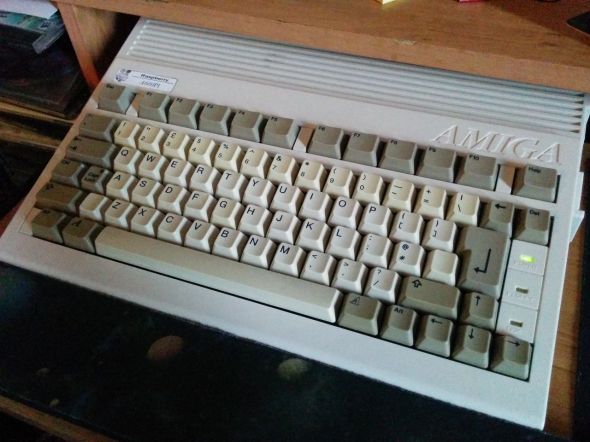
Not so long ago I posted an article on converting a broken Amiga Joystick into a working USB controller. In todays blog, I’m going to cover converting an old Amiga tank mouse in to a USB device. Before any of my fellow Amigans start shouting at me for desecrating a piece of retro tech, I’d like to state the mouse was pooched, the internal micro switches had clicked their last. Sure I could have repaired the switches, but I wanted an Amiga mouse for my AmigaPi and I doubt the world will miss one less yellow A500 mouse.
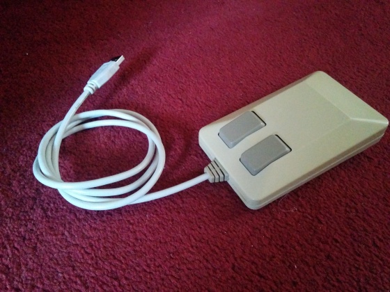
The first thing you’ll need is a broken mouse, please don’t bust up a working mouse, that’s just wrong and a waste of a good device. Next you’ll need to find a donor USB mouse, preferably something small, compact and simple in design. Essentially you’re looking for a budget mouse, the sort you might find in a 99p store. Below is a photo of the mouse I used, don’t worry if it has an internal LED, we can easily snip that out. Next we’ll need a beige USB cable, pick a length that suits your needs preferably something that will connect to the computer and leave enough room for the mouse to sit comfortable on your desk. If you’re still unsure, go for a 1m or 1.5m length cable as you can always trim it down to suit your needs.
We now have the essentials for making an Amiga USB mouse. Unfortunately I can’t walk you through the whole process, as it all hinges on the USB mouse you bought for the conversion. Initially you need to take both mice apart, and remove the electronics from the Amiga mouse. The only parts of the tank mouse you need are the main shell and the flexible plastic sheath around the mouse cord. The best way I’ve found to remove it, is by cutting along the under side with a sharp blade and pulling the cord out through the cut.
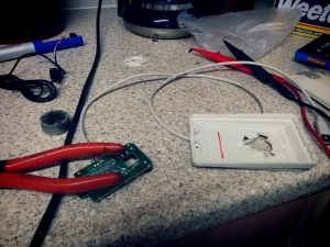
Let us turn our attention to the USB mouse, with the lid off you should have a good view of the PCB. The first thing you need to do is check the pinout of the cable because soon you’ll be removing it. To do this, you’ll need a multi-meter so you can perform a signal test on the each wire going from the connection point on the PCB to the pin inside the connector on the other end of the lead. I find it best to draw a simple diagram of the USB cable with the connector and the four pins laid out. I then jot down the corresponding colour wire for each pin.
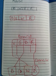
A rough sketch can save a lot of time
Usually this is red, black, green, white, but not all cables are the same so been warned. Once you know the colours and where they go, you need to cut the cable leaving roughly 2” inches coming from the PCB as we’ll be using the remaining wires to patch in the new cable, matching red to red, black to black etc. However if you wish to you can completely remove the old cable by de-soldering it from the PCB and solder your new cable directly to the board. This makes for a neat and tidy finish, but it can prove a challenge depending on your soldering skills. So if in doubt, stick to my suggested route and leave some of the old wire in place. This way it will be easy to match up all those colour wires.
Assuming you are happy with the length of your new cable, trim back the outer sleeve and expose the four inner wires. You should have something like red, white, black and green, if your cable came from China you might find you have blue or even an orange in place of one of the standard colours. Not to worry, just check with your meter and make sure you know which pin the wire goes to. Hopefully if you’re really lucky it will match the wires on the mouse, otherwise you might end up with green as white or red as green. Again jot down the colours on your diagram, matching them up to the respective pins. Usually white and black are voltage, green and red are data. But never take anything for granted, always check!
Once you have the mouse rewired, hook it up to your computer and confirm its working. If nothing happens, check your pin out again.
The chances are your mouse came with a scroll wheel and depending on your skill level, you can either remove this with a hot air gun or use tin snips to remove the parts holding the wheel in place. Just be mindful that you don’t damage the traces on the underside of the PCB. A little wiggling is fine just try not to tear the components right off the board as that would be very bad. Assuming the scroll wheel is now removed, hook the mouse up to a computer and check that it’s still works. Hopefully it does, if not, check you haven’t broken and traces. I’ve make two Amiga mice so far and neither had an issue when the wheel was removed.
If you mouse came with a silly blue or red internal LED (note not the optical sensor!) You can snip it off, as the tank mouse doesn’t need lighting up internally. Your optic sensor does use a red led which is directed into a lens, don’t under any circumstances mess with it!
Here comes possibly the hardest part of the hack, inserting the new PCB into the tank mouse. Initially it won’t fit, for a start the optics will sit to high off the ground to be any good. So you’ll need a Dremmel to cut and sand the inside of the tank mouse, removing any lugs or protruding bits of plastic that are in the way. I’ve included a
Use a Dremmel to gut the inside of the mouse case.
photo to give you an idea of what it should look like, on both the mice I modded I had to superglue the cover ball cover in place. Depending on the donor mouse, the PCB might be too large for the inside of the Amiga mouse housing. If this happens you will need to trim the PCB with you Dremmel and a cutting disc. Regretfully I can’t walk you through this part as designs differ from one device to another. Usually trimming the board breaks the ground plane, you’ll need to do a little trace work with some wire to get things reconnected. Either way, you’ll have to get creative or find a friend to help you. Alternatively find yourself a donor mouse with a small PCB.
When your happy with the bottom half of the tank mouse, use a bit of blue tack and press the pcb down temporarily so that is sits inside the housing. Hook it up to your pc and take it for a test run. How does it perform? Is the cursor jumping about or shaking? If so, the optical sensor is probably sitting too high. First try pressing down the PCB with your thumb, does it improve? If it does, you might be able to get away with hot gluing the pcb while pressing it down with your thumb. Once the glue sets, the board will remain where it is. Otherwise use your dremmel to shave off a little more plastic before gluing the board in place.
Before you go gluing the board in place, we need to address the mouse buttons. You can do this one of two ways, either with a set of large micro switches or a pair of lever micro switches. The latter recreates the clicky sound of the tank mouse really well, but either will do the job just fine. Now returning to the PCB, you will need to remove the existing switches. As they will likely be too far back and not sit in the same place as the original Amiga buttons. You can either de-solder them or once again snip them off. I can’t stress the importance of being gentle at this point, if you damage the traces on the board at this stage you’ll have a hard time recovering the mess, so take it slow!
With the old switches removed, you can begin wiring in the new ones. Remember the new micro switches need to sit where the old amiga switches did inside the case. If you still have the original tank PCB, use it for comparison. If it helps, use a marker pen to drawn on the inside of the mouse case, so you have some guides to follow. Blue tack is your friend and will allow you to stick the switched down while you line them up with the mouse buttons. Once you have them lined up, you’ll need to wire them up to the new PCB. The wires will only need to be short and while it’s a little tricky to get everything sitting right, with a little time and patience it can be done, trust me I’ve done this twice.
With the new buttons wired up, you’ll need to test the mouse again by connecting it to a computer. If everything works, we’ll move on to the final stage, gluing all of the components in to place. It is up to you but I would strongly advise using a little blue tack to stick everything in place temporarily. Place the lid on the mouse and see if the mouse buttons work. Hopefully they should be clicking away inside the mouse and working just like the original. If things aren’t going exactly as planned, don’t worry because we used blue tack. Just pop open the mouse and adjust the switches a little until they are aligned with the plastic buttons build in to the upper lid. When you satisfied, remove the blue tack and use hot glue to fix everything in place. If you’ve only used a tiny bit of blue tack and don’t want to risk moving anything you can always glue the parts in place as they sit.
Finally with the buttons and PCB fixed in place, you need to put the flexible plastic piece back around the mouse cord. Simply peel it open using your thumbs and slide the cable inside. Because this collar piece is meant to keep the cable from pulling out of the mouse, you will need to use some glue to fix the cable from slipping up and down inside the collar. I did this by inserting some glue in the cut I’d made, not only does this hold the cable in place, but it also fixes the collar back together. Once the glue sets, it will stop you pulling the wires out from inside your mouse. Still, I’d recommend against holding the mouse by the cord.
All that is left to do now is to screw the mouse back together and take it for a spin. If you’ve been testing it a every step, nothing should have gone wrong. Hey presto you have a new Amiga USB mouse!
Converting an Amiga Joystick to USB
Posted: June 1, 2016 Filed under: Amiga, Commodore, Linux, Raspberry Pi, Retro gaming, Vintage Computers, Windows | Tags: Amiga joystick hack, db9, raspberry pi, usb, usb joystick conversion 3 Comments Readers of my blog will probably have seen the Amiga 600PI I built not so long ago, using a Raspberry PI 2 under the hood. Out of all the projects, I honestly have to say this was a labour of love and a lot fun project to build. But like any build, there are the obligatory tweaks that must be made to fix things that might have been missed the first time around. Issues that only became obvious after using a build for a week or two. Which is pretty much how it was for me with the AmigaPi.
After using the AmigaPI for a couple of weeks, I began noticing one or two problems. First on the list, wasn’t so much a hardware problem as software. UAE4ARM is the de facto Amiga emulator for the Raspberry pi, in shorts it’s pretty amazing. But as fantastic as it is, there is yet to be any support for remapping the keyboard. This is useful if you like playing games using the cursor keys or say your old skool and prefer using the good old Spectrum controls Z,X,O,P. At the time of writing, this still isn’t an option, which means its still isn’t possible to make use of the built in joystick ports on my KeyRah V2 interface. Sadly it seems no matter how much people plead for the feature to be implemented, those bringing UAE4Arm to the Pi are focusing on performance over functionality. Which is understandable, as any good emulator requires a decent level of real time performance. Afterall nobody wants to play Amiga games at a snails pace with choppy sound. But in the pursuit for good performance, other features have been neglected. Making UAE4Arm a good attempt, but still vastly lacking when compared to FS-UAE or Win-UAE. Both of which offer a far more advanced level of configuration, we can only hope that UAE4Arm will one day follow suit. Given the number of people using their Raspberry Pi for gaming, it would be a missed opportunity if it didn’t.

Controller of choice for most Retroarch fans
In the meantime the only way to play games on UAE4Arm is using a controller, usually this means hooking up an Xbox 360 joypad. I know a lot of people use these on their RetroArch gaming setups as they’re easy to get hold of. Chances are if you own a 360, you already have one laying about the house. However for me, seeing one hooked up to an Amiga 600 seemed as out of place as a Chippendale in a nunnery.
My AmigaPi needed a proper looking joystick, not some Microsoft rubbish. Now there are a couple of ways this can be achieved. Firstly, you can purchase the ready made USB Competition Pro by Speedlink. It looks just like the original, except for the USB connector on the end of the lead. I did seriously consider getting one of those, however digging a little deeper, I discovered more then a few people complaining about lack luster performance. While opinions on the internet are ten a penny, usually where there’s smoke, there’s fire. And at £20 a pop, I didn’t fancy finding out which opinion was right. Especially when I was pretty confident that I could build my own joystick for a fraction of the price.
Buiding A Joystick
The first thing I had to find was a bust Amiga Joystick, I certainly wasn’t about to break a working one just for a hack. At least taking something that is broken and giving it a new life, you’re recycling and not just throwing it in landfill. Luckily in my loft I had a non-working Cheetah 128, which had been
a spare for my Spectrum, until it died.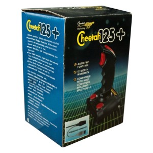
Taking it apart, I was surprised with the simplicity of the internal workings. Unlike some of my quickshot sticks, the Cheetah use simple metal pads to create open and shut gates. Press forward on the joystick and two metal pads would connect to make a circuit. Luckily for me, this would actually worked in my favour, as it would make converting the stick to USB pretty simple. The only problem now was finding the right sort of USB controller. Scouring the net, I found one company that sold a custom analogue to USB adapters, however they wanted £16! I thought this was a little pricey for a single sided, through hole PCB with only chip. It was after all, doing essentially what all the cheap Chinese controllers were doing – translating the inputs from a series of switches / buttons into something the computer could understand as UP, DOWN, LEFT, RIGHT and FIRE.
Ebay is full of USB controllers styled after SNES, NES and 360 joypads, which you can pick up for as little as a few quid. I was pretty sure one of these would contain everything I needed to convert the Cheetah to USB. So biting the bullet, I bought myself one and waited for it to arrive in the post.
A Note on Retro Game Pad Copies

Clones, not always as good as the originals.
After arriving at my doorstep, the first thing I noticed was the quality or lack of it Looks were pretty much the only thing the USB pad shared with the original super Nintendo controller. Unlike the latter, the build quality was cheap and flimsy and not at all solid as you’d expect. A quick game of Super Frog on the Amiga Pi quickly revealed how bad it really was, with the D pad often mashing two directions together. Resulting in a lot of unintentional left and right jumps that left me crying for it to end. After ten frustrating minutes I’d had enough and unplugged it. After seeing how rubbish it performed, I felt less guilty about scavenging it’s innards for my joystick mod.
Fitting A Square Block In A Round Hole
Inside the controller, I was faced with a major problem. The joy pad wasn’t constructed anything close to how I’d been expecting. Spanning the full width of the pad was a single PCB, populated with contact-less switches. I’d foolishly been expecting the pad to use mechanical switches, which I could have easily rewired. However a friend later explained to me that a lot of things these days are built using single a PCB to cut down the cost on components. In light of this revelation, I faced having to solder to the surface of the board. While not my  preferred way of doing things, I’d just have to like it or lump it. If that wasn’t bad enough, the darn PCB turned out to be 2cm wider then the base of the Cheetah. I’d have to work some serious magic with my Dremmel if it was ever going to fit in the base.
One of the hazards with chopping up a PCB, is that they don’t usually work afterwards, not without a bit of rewiring. Such as reconnected broken ground planes etc, which are needed for the circuit board to function. Lucky for me the design was pretty simple, but I was still thrown a couple of times, chasing the ground. Having never attempted anything like this before, it was a learning process for me, figuring out how the board worked and where best to solder to. This was especially true, as I began cutting portions away to make it fit inside the base. After removing almost all the direction pads and three of the fire buttons, the PCB was finally narrow enough to fit inside the Cheetah, hurray!
 If you fancy trying your hand at hacking your own joystick, my advice is to take your time, don’t rush and make a photographic record of your progress. Pictures can come in really handy if a wire pops out and your left wondering where the heck it came from!
To reduce the number of wires I had floating around inside the joystick, I shared the ground from one point on the PCB to all the other contacts. Interestingly, unlike other joysticks of the day, the Cheetah uses a cloverleaf for the main directional stick (pictured left). The only other joystick I know that shares this design, is the original Sinclair sticks that came with the grey Plus 2. This design actually made wiring everything up a lot easier, as its much simpler than those with internal switches. Beneath the star shaped metal plate are four contact screws, which represent UP, DOWN, LEFT, RIGHT. Using wire I’d stripped from an old IDE cable, I hooked the contacts up to those on controller’s D-pad. This is when having photo’s comes it really handy, as more then once I lost my way with the traces on the board. But consulting some photos, I figured out what I was doing wrong and soon had UP going to UP, LEFT going to LEFT and so on.

IDE cable is great for fine work like this
In theory, when connect to a USB port, the board would register the movement of the stick just as it had the original D-pad. While I recycled a lot of the Cheetah’s original wiring, I also used a lot of wire from an old IDE cable. Not only is it very flexible, but its also very low gauge, which makes it perfect for soldering to the tiny traces on the joypads PCB.
First Test
After the wiring, came the next challenge: hooking the joystick up to a USB port and hoping it worked. I’d already had the pad albeit in original form, connected to my Windows PC. It worked straight out the box with a minimal amount of setting up. Hooking it back up, I was pleased to find everything worked first time! 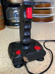 After a game of Stunt Car (obviously!) on WinUAE, I began wondering about the buttons in the base of the Cheetah and whether or not they could be made to work. True the wiring inside was more jammed than a sumo wrestler in a phone box. But I wasn’t satisfied, I wanted those darn buttons to work. After all, the natural way of holding the Cheetah was with both hands. The whole time I’d been playing Stunt Car, I kept feeling the urge to use the lower buttons instead of the trigger.
Achieving this feat took some hacking, I can tell you. First I had to find room for the micro switches. There was barely any for them to sit between the PCB and the lid, the only option was to cut out a cavity in the buttons for the switches to sit inside.

From left to right, a converted button next to one waiting to be altered.
As you can see pictured, this was finally how the buttons looked, with the switches recessed inside the red plastic housing. It took several failed attempts on my part, before I found the right depth for the switches. But eventually I was firing nitros in Stunt Car without a hitch. I think the scariest moment was when I screwed everything together. With the top and base finally secured, I was worried everything would squashed together. Luckily, I didn’t need to worry, as it worked fine.
And here is a final image, which I think pretty much captures my feeling at the end of this hack.

This trophy’s bigger then my head!!
The Raspberry A600PI AMIGA
Posted: November 6, 2015 Filed under: Amiga, Commodore, Linux, Raspberry Pi, Retro gaming, Vintage Computers | Tags: Amiga, Amiga Pi, commodore, raspberry pi 27 Comments
What do an Amiga A600 and the Raspberry PI have in common? Well at the time of their release, both were considered small micro computers. So what do you get when you combine the quad core power of a RPI-2 Model B and the compact design of an Amiga 600? In theory, a compact quad core Amiga, that runs Linux. But that’s just a theory right? No one’s actually gone to the trouble of making such a freaky hybrid have they? Well actually yes, in fact plenty of people have been putting Raspberry Pi in all sorts of things, ranging from Spectrums, C64s, toasters and pants. Ok I made that last one up, but you just wait, the day is coming when someone will develop digital ‘smarty’ pants. That day is coming my friend. Most of the time the A1200 and A500 are utilised for modding purposes, most likely because of the space afforded in both machines.
Measuring in at 14” by 9.5” and 3” high, the A600’s small size works against it for modding purposes, it also lacks a full size keyboard, so there is no numerical pad. Even back in 1992, the A600 came under fire from people criticising the short comings of its design. For a machine intended to replace the aged A500+, it did a pretty poor job in many respects. Later the managing Director of Commodore UK, David Pleasance, would describe the A600 as a “complete and utter screw-up”

David Pleasance – Not the A600s biggest fan
As a kid at the time, I recall thinking the A600 looked like a waste of time compared to my expanded A500+. It wasn’t until later that year, when I saw the A1200 in Amiga Format, that I began drooling. Fast forward 23 years and here I am staring at a 600 case, wondering what I can do to it. In my head, I was picturing a useful Linux machine capable of going online, playing games and running UAE (Ultimate Amiga Emulator). I had a Keyrah sitting on the shelf begging to be used, so what am I to do? Initially, I did nothing. Back when the Raspberry Pi was first released, it was intended for hacking LEDs & light sensors together or acting as the brains inside an electronic project. It wasn’t meant to be a desktop computer, it simply didn’t have the memory or power to handle it. Gradually, the Pi evolved, more RAM was added, the design was refined, software was optimised, until finally the Foundation released the Raspberry PI 2 Model B. Upgrading the tiny computer with a quad core Arm Cortex A7 processor, this update opened the door to variety of new possibilities, including my shelved Amiga project.
The RPI 2 Model B is a beast compared to the B+
The Pi is very affordable when you compare it to other SBC boards. It also has the benefit of a rich and active community. Not to mention the copy cats that have emerged since its release. While some people might critisise them, I think it’s ace – competition is healthy. Children are once again wiring up things to their computers, learning how to program, learning LOGIC. Some of these kids might go on to shape our future and possibly develop the next breakthrough technology. But in the meantime, here at ByteMyVdu, we are more interested in seeing if a RPI2 can be merged with 20 year old Amiga…So read on and find out.
In the Beginning
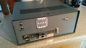
Even before I started drilling or ordering parts, I knew one thing for sure, I wanted the hack to be neat, not just that, I wanted the Amiga PI to look no different to a regular Amiga. I wanted people to see it sitting on my desk and think it actually was an Amiga running Linux. But how to go about it? After all the RPI has vastly different ports to the Amiga. Instead of serial and parallel, we now have USB, and in place of composite there is VGA or if you prefer DVI / HDMI. There is also the RJ45 port, allowing you to hook the PI up to your network. Back in the day, the Amiga used serial or a PCMCIA modem to talk to the outside world. One thing was for certain, the back of the Amiga was going to look vastly different with all the new ports and connections, utilising the existing holes cut in the case would only end up looking odd.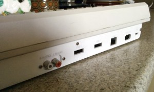 So I decided to craft a new back panel from 3mm acrylic. Taking measurements of the rear panel of the A600, I spent a Saturday designing a vector on my Macintosh Classic. Originally I’d been planning to write an article for BMV about the Manchester Play Expo, but the idea popped in to my head that it would be more fun to design the back panel. Surprisingly the process was very easy and transferring the design over to the main computer went without a hitch. So anyone who says that 68k Macs are useless really needs to have a rethink.
With the back panel cut from white acrylic, I began buying the cables necessary to extended the ports of the PI to the rear of the Amiga case. I shopped on eBay for all the things I needed, while Amazon might have stocked them, I wasn’t so enthusiastic about buying from them after being burnt in the past.
The list of parts I needed was as follows
- 1x Panel mountable, RJ45 extension cable
- 2x Panel mountable USB extension cable
- 1x Panel mountable Micro USB female to male cable
- 1x 3.5mm stereo to female RCA phono cable
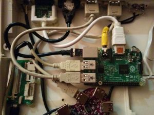
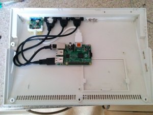 With all the cables together, I went about installing the new back panel. Having already cut out the back from the Amiga case, I offered the new panel up to see how it look. Fortunately for me, my measurement had been pretty good and the new panel fit nicely against the back of the A600. Once the case was together, it was time to attach all the cables, screwing and gluing them in place where needed. While doing this, I discovered a handy Y shape USB splitter on eBay, turning one USB port in to two. It was only after I had installed the cable, that I discovered the splitter was only good for charging. No matter what I hooked up to the ports, nothing would appear. The only device that DID work was a mouse, pretty much cementing the fact, that the cable was complete rubbish. Luckily I’d bought two USB extension cables prior to seeing the splitter, so it was just a case of swapping the cables around. Even though I had glued the splitter in place, I was still able to extract it. With the new cables installed, I now had two fully working USB ports on the back of the case. As for the USB splitter, it went in the bin. The next step was installing the Keyrah. This little device from IndividualComputers turned the Amiga keyboard in to a USB device, enabling me to use it on the PI, so it was important I found space inside the Amiga to accommodate the PCB. Imagine my surprise when I discovered the joystick ports on the Keyrah lined up perfectly with those on the 600 case. I’m not sure whether this was intended, needless to say it made installation easy. The Keyrah does sit rather close to the floppy drive, which might cause problems in the future, should I wish to fit a disk drive. Later models of the Keyrah have a slot for connecting the keyboards ribbon cable, but mine is an early revision. So instead of a slot, the contacts are printed on to the PCB and a bar is used to hold the ribbon cable in place. All I shall say on this earlier design, is that I understand why they changed it. Every time I open the AmigaPI the ribbon cable would move, taking out the keyboard.
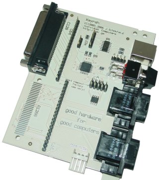
Keyrah, handy kit so long as you leave it alone.
Because of the limitations of the A600 keyboard, the Keyrah has an on board switch, that swaps between two keymaps. Essentially giving you access to a full keyboard. Because the Keyrah resides inside the Amiga, I’m not sure exactly how they expect me to access the switch. Unless I was meant to cut an ugly hole just below the floppy drive, hmm I don’t think so! Perhaps at a later date, I will wire up a new switch and mount it on the back of the Amiga. One final aspect to wiring up the Raspberry PI with the Amiga case, was case lights. In what has to be the most hairy bit of soldering I’ve done. I removed the surfaced mounted LEDs from the Raspberry PI to gain access to the solder points below. Then using some IDE cable, I attached wires from the motherboard directly to the legs of the LEDS. Holding my breath, I turned the machine on and what do you know, the power and drive light came on. Not the sort of soldering I want to do on a regular basis, as my heart was in my throat the entire time I was soldering to the tiny PI board.
Power

Yes, they work!
The combined power requirements of all these devices undoubtedly pushes a PI to it’s limits, at it’s best the PI has 1.2A devoted to the USB bus. If one or two of your devices are power hungry, the 1.2A cap can quickly become annoying. The only solution is to use a powered hub, which is exactly what I did. Due to the limiting space factor, I tried to avoid using as many connectors as I could inside. Instead opting to chop the ends of cables and solder the wires directly to the points on the hub. The PI hub has a 5v 2A port dedicated for powering the PI, so instead of using the intended USB cable, I soldered wires straight to the 5v and ground. I then soldered them to the power points on the PI motherboard, just below the micro usb power port. I also converted the power socket of the hub in to a female micro USB socket, which I glued to the back panel of the Amiga case. This meant I could continue using PI specific power supplies.
Feeling Wired
Soldering all these wires together, I made a very rookie mistake, by not taking in to account the resistance of the wires on the whole circuit. This became apparent the first time I booted up the PI. Even though I was using an official Raspberry PI psu, the square rainbow under volts icon appeared in the top right corner of the screen. Running a volt meter over the ground and 5v pin on the GPIO port, I discovered it was reading around 4.5v, not the 5.15v that I was expecting. If there is one thing I learnt during this build, it is that USB cable makes a poor substitute proper gauge wire. If you want to reduce high levels of resistance, make sure to use a decent gauge wire.
I learnt this lesson the hard way, leading to me to rewire everything a second time. After which the voltage over the GPIO port was restored to just over 5v. The original psu for the PI hub is rated at 5.2V 2A, which is more then enough to power a PI under normal circumstances. In the AmigaPi’s current configuration, it appeared just enough to power everything, the under volts icon appears whenever the rear ports are in use. With this in mind, a 3A power source will likely be on the cards.
Software
War, never been so much fun!
Under the hood the AmigaPI runs the latest version of Raspbian, I have also installed UAE4ARM, the lastest Amiga emulator for the Raspberry PI. Not only does it receive regular updates, but it quite possibly the fastest Amiga emulator you can get on the PI. Configuring it to work can be a little tricky and keyboard support is not all there yet, but anyone who spends time reading on the Raspberry forum have little trouble getting it running.
There are a surprising number of Linux games available for the PI, ranging from Doom clones to arcade Galaga, you can even get point and click adventure games such as Beneath a Steel Sky. All of these work fine with the Raspberry Pi and are definitely worth a look at. DOSbox is also available I’ve yet to test it out, so I can’t say how good it is at emulating a DOS machine. But if UAE is anything to go by, it will hopefully manage 486 games without breaking out a sweat.
Being a Purist
As I mentioned earlier, I wanted the AmigaPI to look like an Amiga, with working Joystick ports, a functional floppy drive and PCMCIA port. Admittedly the rear of the computer looks different, but that couldn’t be avoided. The PI doesn’t have a serial or printer port like the Amiga, nor does it have an composite or RF connector. The only option I had was to give the new back panel an Amiga feel, which is why the power connector is in the far corner, why is has phono connectors for audio and two USB ports, in place of the old serial and parallel ports. The floppy drive is still a work in progress, as the floppy to USB adaptor I bought is sitting on my desk untested. Until I have a new power supply, I don’t wish to risk corrupting the SD card by causing a brown out. But hopefully in the near future the familiar click of a floppy drive will return to the old A600 case. Fitting the Amiga PI with a PCMCIA port seems a little redundant to me, as I had an old CF card reader kicking around, I decided to compromise. After all, when my A1200 isn’t on WIFI, it spends most of its time with a CF card adaptor stuck in the side. Equipping the AmigaPI with CF, meant I could easily transfer files, pictures, mods and ADFs back and forth between the AmigaPI and my regular Amiga’s. Something I envisioned being pretty useful at LAG meetings, when we are taking pictures of the meeting.
Final thoughts
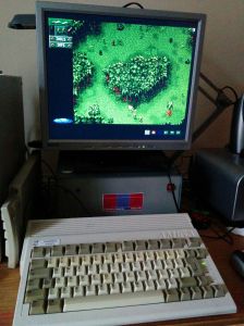
I honestly can’t believe I’ve finished this project, that I’m sitting here at this moment, typing on what looks like a regular Amiga 600. Except the badge bares a berry shaped logo and next to it, reads Raspberry A600PI. Ok it’s not a next generation Commodore product, but then when are we likely to see that happen? The reason people are still rocking Commodore products is because of the mindset behind them. The passion that drove the team who made the Amiga, still lingers, the embers faintly glowing from a fire that blazed decades ago. All I know DO know, is that I get a certain buzz from using a computer that fits inside a keyboard. Unlike my Windows 7 tower, I can thrown the A600PI in my bag and take it with me and who knows, maybe even play a game of Sensible Soccer over at a mates. Yes its dirty filthy nostalgia but on top of that, it’s turning the PI from a mass pile of wires, in to a compact, usable computer. I only have to connect power, VGA and mouse to get the AmigaPi up and running. Everything I need, is self contained within the confines of the A600 case. With a regular PI, I have to find my VGA to HDMI adaptor, WIFI dongle, powered hub, keyboard and mouse, before I even begin to think about powering it on. In short, its a real faff, but not any more!
So if you’ll excuse me, I feel the need to play Cannon Fodder now, till next time keep on geeking!!
No Amigas were harmed during the making of this project, but one ropey looking, long dead 600 was given a new brain.
Monkey Island 25th Anniversary
Posted: October 10, 2015 Filed under: Amiga, Commodore, Retro gaming, Uncategorized Leave a comment
Can you believe it? The famous Lucasarts title, celebrated its 25th birthday!
Released on October 1990 for the Amiga, Atari ST and Macintosh to name a few. The game was a smash, with critics of the time praising its humor, game play and graphics. So popular was the title, that is spawned a sequel, Le’chucks Revenge. LucasArts released a remake of Monkey Island in 2009 for Windows, iOS, Xbox 360 and PS3. This ‘special edition’ featured new hand-drawn visuals, a remastered musical score, as well as voice work for characters and a tips system to aid struggling players. Developers included a function in the remake, allowing players to switch between the 2009 and original 1990 audiovisuals.
Ron Gilbert first conceived the idea for Monkey Island in 1988, his frustration with other adventure games of the day led to him making it impossible for the player to die while playing. Something that could happen to you without warning in Sierra’s point & click adventures. Ironic that the first ‘point&click’ I played on my A500+ was Space Quest. After playing through that game, I played Monkey Island with an unshakable certainty that I would eventually wind up killing Threepwood. So when he first fell off a cliff in the game, I stared at the TV with despair, then bewilderment. When a few moments later, he bounces back, saved from death by a rubber tree. The playful, parody of the Sierra “Game Over” screen is a nice touch and typical of the humor found in the Monkey Island series. To which Gilbert, Schafer and Grossman are responsible for. Together they wanted to develop a more accessible game compared to previous LucasArts titles, where amusement and exploration are key elements. Perhaps it is this approach that has made the franchise so popular, Monkey Island was innovative game for its day and is still enjoyable today through the 2009 remake. If you’ve never played the game before, I highly recommend buying a copy via Steam.
Monkey Island: Special Edition is currently available on Steam for £6.99
Monkey Island Steam link

Retr0-Brite The On Going Saga
Posted: September 5, 2015 Filed under: Amiga, Commodore | Tags: Amiga, retr0-brite, retrobrite Leave a commentTo say that I’ve tried my hand at brightening up some of my older machines would be an understatement. I’ve tried doing it to an Amiga 500, an 1200 and even an old Macintosh ADB keyboard that had gone rather yellow. The only success I’ve had to date, was with an Amiga mouse which I changed from smoker’s yellow to having a slight case of jaundice. I’ve never had the shocking ‘Wow’ factor results that other people have posted online, it’s been something of a white whale. So it’s no surprise that every now and then I find myself coming back to have another go, this time with two Apple Pro USB keyboards. Less than 10 years old, both look like they came from a heavy smoking environment, when in actuality they were white when I put them in storage. Clearly, being boxed in the attic has not done them any good. I started with the worst of the two and began stripping it down, removing the keys into an ice-cream tub. I then painted the main keyboard with some 40% Blonde hair bleach, which you can pick up from Boots and Home Bargains here in the UK. In the past I have tried using solutions of Peroxide, mixed with wall paper paste. This ended up ruining the A500 case I had tried restoring. Using the little gold bottle of hair bleach had been suggested to me by Merlin. No not the Wizard(!) but the Amibay username of the chap who came up with Retr0brite to start with. After a lengthy discussion via Skype, where I felt increasingly in over my head, Merlin aka Dave Stevenson finally said I should forget all about mixing bottles and just go for the easy approach. This was great news as up until then I’d begun to think to do Retr0brite you required a PHD in potions and wizardry.
So cancelling my application to Hogwarts, I waited patiently for sunshine and in Yorkshire you have to be patient. Fortunately I was able to bag two good days of sun, albeit with the occasional shower. The results took me by surprise. While the main body of the keyboard had been covered in cream peroxide and wrapped in cling film. I’d submerged the keys in a solution of 40% vol peroxide and hot water, with a little oxi vanish mixed in. The keys had only slightly brightened up, where as the keyboard while not restored to its original ivory white, was noticeably less yellow.
For now, I’m biding my time until we have more sunshine. Then I plan to apply cream to the keys as well and see what the results are. For now I think it is fair to say that I’ve given up using liquid peroxide, in favour of using cream.
So keep watching this space folks!
Slow posts, Free Computer and Game Reviews
Posted: May 7, 2015 Filed under: Amiga, Classic, Commodore, Retro gaming | Tags: a500, Amiga, game review, n64, return to atlantis Leave a commentThings have been a little quiet here on BMV, but that isn’t to say that there hasn’t been any geeky goings on behind closed doors. At a recent Amiga club meeting, a member of the public brought in their old Amiga rig and software. Left to gather dust in their attic, they brought it to LAG hoping to find it a new home. By sheer coincidence I had brought along my own Amiga 500 Plus to the LAG meeting, along with an external hard drive I was trying to install games to. Having owned an A500 back in the day and only ever used the floppy drive, I was eager to experience all the IDE goodness. Sadly my Amiga was choosing not to work with the GVP expansion, so when the offer came of a free boxed A500, I jumped at the chance. When I opened the boxed, I discovered it was complete, with manuals and polystyrene packaging, just as it had been the day it was sold. From what I gather the A500 is faulty, so I will have to check it out when I can get around to it.
Along with his A500, the gentleman brought in two boxes worth of Amiga games. Sifting through them, I found titles such as Desert Strike, Monkey Island, Rocket Ranger and Castle Master. All classic games in their original boxes. I goes without saying that a number of the games ended up coming back home with me and it’s a sure thing I will be reviewing them here on my blog. Sure there are plenty of places online filled to the brim with Amiga game reviews. But as I seldom review games, I figured what the hell, why not have a go. Besides that is what ByteMyVdu is all about, talking, discussing and reviewing everything old bit of computer kit I can get my grubby hands on.
In the next couple of weeks, I’ll be writing about repairing or trying to repair an Nintendo 64 and also doing a review of “Return To Atlantis”, one of the games acquired at the LAG meet.

Till next time, keep on geeking!
Heating & Good Ventilation
Posted: May 3, 2015 Filed under: Amiga, Classic, Commodore, Linux, Retro gaming, Vintage Computers, Windows | Tags: custom built computer, home computer, MSI Fuzzy, xubuntu Leave a commentNomad Update
A couple of years ago I wrote an article on BMV about a retro themed computer I’d built, designed to look like a Z80 Micro computer from late 70s. The build went pretty well and overall I have to say it was a success. The front panel even had blinky lights! But like many prototypes, there were one or two unanticipated bugs. Today’s article will cover the biggest of them all: heat, and how its ultimately in your own best interest not to ignore it. So pull up a chair, grab a hot beverage and lets get the party started.
Linux offering a serious alternative to Windows
At the heart of the Nomad is an MSI Fuzzy 945GM2 motherboard, fitted with an Intel Core Duo T5500 central processor and 2GB of DDR2 memory. By today’s standards the hardware isn’t very impressive, but powerful enough to run old DOS games, emulate other systems and still provide a decent working system. Windows XP Professional, while not so safe online, is still the best option for running most old software, while still being able to run Photoshop and Illustrator. Due to XP’s vulnerability on-line, I installed Xuntubu along side it, so I had a secure platform for surfing the Internet. Seriously if you have never considered Linux and you are moving away from XP, then I couldn’t recommend it enough. It’s free, open source and runs really well even on a system with limited resources. I also discovered that interfacing my TRS80 M100 via serial is much less of a headache through Linux, than it ever was using Windows.
For those of you that may have missed my earlier article, I originally used an ABS plastic enclosure to house the Nomad. At the time I thought the case would be fine, but later discovered the motherboard was cooking inside the tiny case. So much that the hot glue I had used to construct part of the case has melted and one of the SATA cables was stuck to the underside of the top lid. Using a digital thermometer I’d built, I discovered the inside of the case was reaching close to 85 degrees! Ouch!
Nomad Part 2 Taking Shape
So it was back to the drawing board, I could either find a larger case or replace the MSI board with something cooler, such as a dual core Atom board. Having past experience with Atom chips, my feelings towards them was a little jaded. As low cost CPUs go, they serve a purpose, but I’ve never found them to be that impressive in a desktop environment. I’ve seen Atom based systems advertised as compact desktop replacements, but in my experience, that is a load of old twaddle. Atom powered machines are little more than Netbooks that have been stuffed inside a compact desktop box and we all know what happened to the ill fated Netbook! Using an Atom board was simpy out of the question, for a start I was doubtful it would handling emulating a Spectrum, let alone a Commodore Amiga. I had to stick with using the Fuzzy board, so I needed to find a better case to house the guts of the Nomad. Thanks to the popularity of the Raspberry Pi, eBay is now flooded with project boxes and kits catering for hackers and builders alike. Unlike before when I struggled to find even one case, I was now faced with a torrent of cases to choose from. It still took me over a month to find a decent case that still had that ‘Altair’ look. Advertised as a Raspberry Pi enclosure, I have to say the seller was being modest.
The New Nomad?
To This!
You could probably fit 20-30 Pi inside the one case. Constructed of metal, it would be perfect for the Nomad v2. Cutting out the back and front panels proved to be a challenge, but I had faith in my trusty Dremmel. The new case was double the price of the original plastic enclosure, but for a metal case it was still relatively cheap.
Once it had arrived, I began the process of transferring the guts from the old case to the new one.
Disaster…Panic…Death
A month after the Nomad v2 was built, it randomly stopped working. At first I wondered if my fears come true, that exposure to high temperatures in the old case had damaged the components, leading to the main board giving up the ghost. Exhausting every theory, I couldn’t figure out for the life of me what was causing the machine not to work. In the end, I took the machine over to friend’s, hoping a fresh pair of eyes would see something I hadn’t. Thankfully this paid off, unlike me, my friend Peter went straight for the power supply. Not the one inside the machine, but the external brick I was using to supply 12v to the computer. I’d been so convinced heat had damaged something, I’d overlooked the simplest answer. I later realised I’d overlooked the load the Nomad was placing on the external power supply. The motherboard, CPU and drives needed at least 125watt’s and the power supply I was using fell short by a long way. Before rebuilding the Nomad, I sat down and calculated the systems power requirements and bought a PSU and ATX Pico adaptor better suited to the system. Overall the rebuild has been a success and I always get a special buzz when someone asks about the odd looking machine on the desk.
Amiga Yahoo Email
Posted: September 26, 2013 Filed under: Amiga, Classic, Commodore | Tags: A3000, Amiga, commodore, email, OS4, yam Leave a comment
In the next few weeks I shall be looking at setting up a yahoo email account on an Amiga 3000 and Micro AmigaOne running OS4.1
After learning recently that my Yam guide had failed a fellow Amigan, I have decided to get the proverbial finger out and cover setting up email more thoroughly.
If anyone has any questions or would like me to cover something specific, please feel free to send in a message. I would love to hear from you!
So until next time, keep on geeking!
Micro Amiga One Birthday treat!
Posted: March 28, 2013 Filed under: Amiga, Commodore, Retro gaming | Tags: AOS4.1, Au1, micro amigaone, NC100 3 Comments
This is sort of a belated blog, written back in February. It has been sitting on the NC100 waiting to be uploaded. Sadly ill health, bad weather and life in general took their toll. So here finally is the belated birthday blog of 2013!! Ho ho ho…wait that’s not right!
A recent addition to my collection of computers, is a very shiny Au1, better known as a Micro AmigaOne. A totally unexpected but welcome birthday gift from my father. After a few weeks of playing around with the machine, I have to say I’m very impressed with the latest offering of the Workbench operation system. OS4.2 retains a certain similarity with 3.1 and 3.9, while at the same time it evident some thoughts has been put in to this release. The Au1 is a giant leap from my classic 68k Amiga, having never used a PPC system before. I have to say my first impressions are very positive. On the one hand everything feels just as it does when I’m using my Amiga 1200, but then you have programs such as OWB, which offer as close to a modern day browsing experience as you can find on any Amiga, which is leagues apart from Ibrowse on the old 68k 1200.
One thing is for sure, I’ll be spending some time getting myself familiar with this new computer as well as Workbench / OS4 or what ever you want to call it.
I know one thing for certain, I’m looking forward to seeing what games are available on the PPC Amiga. As well as if they actually make use of the 750mhz cpu and ATI radeon video card. It is certainly a step up from my Picasso II in the A3000.
Written on an Amstrad NC100
Lincolnshire Amiga Group 31st Meeting, repair, repair and game
Posted: March 4, 2013 Filed under: Amiga, Commodore, Uncategorized, Vintage Computers | Tags: A3000, A3000 psu fix, Amiga, Monkey Island 2 CommentsSaturday saw yet another congregation of the Lincolnshire Amiga Group, 11 people where able to make it this time round, which isn’t a shabby turn out at all.

“Nothing says Amiga more then Monkey Island”
While my girlfriend took along her trusty A600 for a session of point & click adventuring, I’d brought along my Amiga 3000 still needing attention and my micro AmigaOne with freshly installed 512mb SDRAM. This time around it finally seemed to be working, unlike last time, when the ram I bought produced errors while surfing the net. Just as I had been warned, the Au1 is a picky little bugger when it comes to ram. Hopefully this time I’ve found a stick of SDRAM that will work. While sitting beside my GF who was enjoying a game of Monkey Island II, I realised after all the time spent setting up the Au1 so that it was working with all the right apps, had completely neglecting the subject of games. This left me sitting at LAG without a game to play. Luckily I had packed my A1200 which had one or two games on the HDD, “UFO: Enemy unknown” being one of them and also one of my favourite Amiga games. Ok I might keep getting wiped out by the Aliens, but there’s something about the isometric game which I find very appealing. I’ve tried playing other newer incarnations of the game, but frankly nothing beats the original for me.
One of the reason I had took along the A3000 was in the hope Gaz would be able to give it a looking over. The man knows a heck of a lot more than I do about the A3000, not surprising when I’ve hardly had one more than two years. In anticipation of meeting up with him, I had printed out the pin configurations for the A3k. My plan was to return the A3000 to its stock settings and then slowly add hardware a piece at a time. Getting it to even boot would be a result, given it would turn on and display nothing at all, except a blank screen!
The last time the A3k had worked, was prior to installing an A3640 processor card and a brand new ZoRAM 128mb card. After installing the two cards, the power supply in my aging A3000 finally decided it had enough and decided to pop, perhaps taking offence to being asked to power more demanding hardware. A bright spark and puff of smoke and the PSU was toast, leaving me with a major problem. Where  the heck was I meant to find a replacement? I couldn’t really phone Commodore for technical support. Fortunately I was in luck, some boffin had worked out how to use a modern ATX power supply in an A3000 and A4000. Glancing at the how-to, it was unlike any project I had taken on before. Now I will take on most things for the hell of it, but playing about with the guts of 240v power supplies and transformers just makes my spider sense tingle. Thoroughly convinced I was going to electrocute myself or fry my Amiga. I spoke to Gaz, who was more than willing to help me rewire a PSU at the next LAG. In the mean time I found a mini ATX psu, the sort found in Compaq and Dell compact office computers. By all counts, it looked like it would fit inside my existing A3k PSU casing, which would keep the Amiga looking original.
After a lot of help from Gaz, the new PSU was up and working, with only a few wires left for me to tidy up, the more hazardous work having been done already. Installing the new PSU in the A3k, I was actually rather nervous, the explosive memory of the old PSU was still in my mind. So I donned a set of insulated gloves before switching the A3k on. With a whir of the fan and a blink of the front LED the Amiga powered on. Except it wasn’t booting from the hard disk drive or posting an image on the screen. Something was up and this time it wasn’t the power supply.
Now we fast forward to LAG 31, remember I wasn’t playing games? Right well instead of a romp of Monkey Island 2, I decided more fun would be had taking the A3000 apart, because that just how rock and roll I am!
Dragging Gaz away from his machine and sitting him in front of the A3000, I explained what I’d done so far and my plan with the jumpers. The print out really wasn’t needed, as he poked his head in the Amiga and adjusted most of the jumpers from memory. See? I told you he knew more about the A3k then I did, any doubters should get to the back of the class.
Switching on the machine I held my breath, a few moments passed then finally the screen came to life! Hurray! My Amiga was alive! It had narrowly dodged becoming a glorified paper weight on the shelf. One after the other we slowly installed the zorro cards until the machine was up and working with my Picasso II video card, X-surf network adaptor and 128mb ZoRAM memory expansion. The new psu was handling everything that was thrown at it, in addition the inside of the Amiga looked no different to any other A3000, aside from a few shrink wrapped wires. Overall I think this mod / repair scores an awesome on my fix-o-meter!
A big thank you has to go out to Gaz for all his help, Rockape for the A3640 and several guys on the Amiga.org forum, who kindly pointed me in the direction of the jumper settings for the A3000 motherboard.
(Written on an Macintosh Plus with 4mb ram & 500mb Hard disk.)
