Psion II LZ Repair
Posted: December 14, 2018 Filed under: Handheld, Uncategorized, Vintage Computers | Tags: LZ64, organiser, psion, psion II, Psion LZ, repair 3 Comments
I thought I would post this sooner than later, as this is something I’m presently working on.
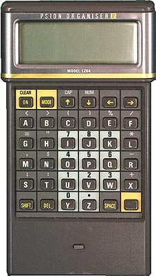
For those who might not be familiar, the Psion II was an early form of pocket organiser produced and sold by the British firm Psion. During its lifespan the organiser went through several versions. Beginning with the CM, a very basic unit with just 8kb of memory and ending with the top end LZ64, which has a 20 column 4 row display as well as whopping 64kb ram.
As part of an ongoing series of pocket computer reviews I’m writing, I have covered several models of the Psion II. Sadly the LZ64 suffers from a persistent and quite irritating whistle, which I believe comes from aging capacitor.
Today I removed all but two of the nine electrolytic caps inside my LZ in a bid to rid my unit of the blasted whistling. Here you will find some info on the capacitors I removed and their location on the PCB. If you own an LZ or LZ64, this information should be useful. As always the same rules apply, you repair your own gear at your own risk. If you set your shirt sleeve on fire, pour hot coffee on the cat or fall out with the postman, you can’t blame me! I’m simply providing this information as is. Hopefully it will result in a silent LZ, except for the for the odd beep and click of course!

Fig.1 A single screw holds the top PCB in place
After you’ve removed the screws and popped open your Organiser, you’ll find the motherboard screwed to the front half of the case. Laying the device face down, unscrew the top board which is held in place by a single screw (see fig1).
The main logic board is still connected to the keyboard via a ribbon cable just behind the pins for the ROM slots. This cable is pretty stiff and will take some gentle persuasion so as to bend the logic board up enough to remove the screws holding the keyboard PCB to the front case.
Once you have the boards removed turn them over so you can view the logical board the right way up. Remember to handle the two PCB’s with care, after all they are 30 years old and tend to be delicate.

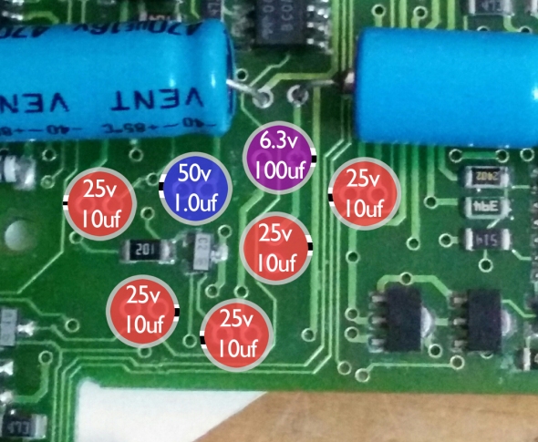
You should now see something similar to fig.2. Note the already exposed pins below the cluster of caps, this is because one of the 25v 10uF capacitors has already been removed from the board.
Using an already warm soldering iron, I removed each cap, recording their values as I went along.
Of the seven radial electrolytic caps, the LZ has;
5x 25v 10uF
1x 50v 1.0uF
1x 6.3v 100uF
For now I’m leaving the two large axial caps in situ, as I want to try the LX with radial caps replaced but the axial caps remaining. If the whistling persists this might indicate which caps are the culprit.
Until the new caps arrive there isn’t much more I can do, so I shall leave you with this pretty diagram, which shows the values and orientation of each cap.
-Keep on geeking!